A Control valve is used for controlling the flow of fluid by varying the size of the passage of flow according to the controller and enable direct control over the flow rate. This results in control over process quantities like temperature, liquid level and pressure. It is termed as a final control element in automatic control terminology. The optimal functioning of the control valve not only exists of sufficient body & seat tightness but more important, the total ‘performance’ of the valve and its controls. For an accurate and reliable working effect the valve body, actuator, positioner, regulators, etc. most work in strict harmony. Therefore, in this article, an introduction to control valves types, working principles, main parts, inspections and tests of control valves are described.
1. Types of a Control Valve
A: Based on Pressure Drop Profile
i. Low Recovery Valve
These types of valves regain a very small amount of static pressure drop from inlet to outlet’s vena contracta and are characterized by a high recovery coefficient. Examples: angle valve, globe valve.
ii. High Recovery Valve
These types of valves regain most of the static pressure drop from inlet to outlet’s vena contracta and are characterized by a low recovery coefficient. Examples: Butterfly valve, ball valve, plug valve, gate valve.
B) Based on Movement Profile of Controlling Element
i. Rotary Valve
Rotary Valve: In this type of valve the disc of the valve rotates. Examples: butterfly valve, ball valve.
ii. Sliding Stem
In this type of valve, the valve plugs or stem moves in a straight line motion or linear. Examples: angle valve, globe valve, gate valve, wedge valve.
C) Based on the Medium of Actuation
i. Manual Valve
These types of valves are actuated by handwheel.
ii. Pneumatic Valve
These types of valves are actuated using a compressible medium like hydrocarbon, nitrogen, or air with a piston-cylinder or piston spring-type actuator and a spring diaphragm.
Control valves can be differentiated on the following basis:
- Hydraulic Valve: These valves are actuated by a non-compressible medium like oil or water.
- Electric Valve: These valves are actuated by an electric motor.
A wide variety of control operation and valve types exist but have mainly two forms of actions which are the rotary and the sliding stem. But the most common type of control valves is V – notch ball, sliding stem globe, angle types and butterfly valve.
D) The Common Types of Control Valves are
i. Sliding stem
- Angle body valve
- Globe valve
- Angle seat piston valve
ii. Rotary
- Ball valve
- Butterfly valve
iii. Other
- Diaphragm valve
- Pinch valve
2- Working Principle
The closing or opening of automatic control valves can be done by pneumatic, hydraulic or electrical actuators. With modulating valve which is set at any position between fully closed and fully open, the favorable degree of opening is determined by the valve positioners.
In general, air-actuated valves are used because of their simplicity since they require only compressed air supply, but the electrically operated valves need additional switchgear and cabling and hydraulically actuated valves need return lines for hydraulic fluid and high-pressure supply.
Pneumatic control signals are based on a pressure of range 0.2 – 1.0 bar and an electrical signal of 4mA to 20mA for industries or 0 V to 10 V for heating, ventilation and air conditioning systems. Electrical control includes a smart communication signal which is superimposed on 4mA to 20mA control current, so that valve position verification can be signaled back to the controller. The highway addressable remote transducer protocol, Profibus and field bus foundation are the common protocols.
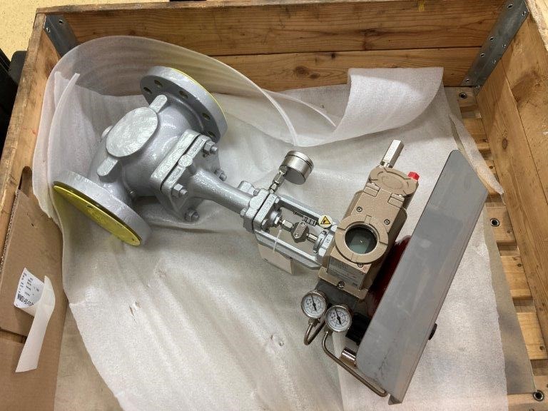
3- Main Parts of Control Valve
1. Actuator: It is used to move valve modulating elements like butterflies or balls.
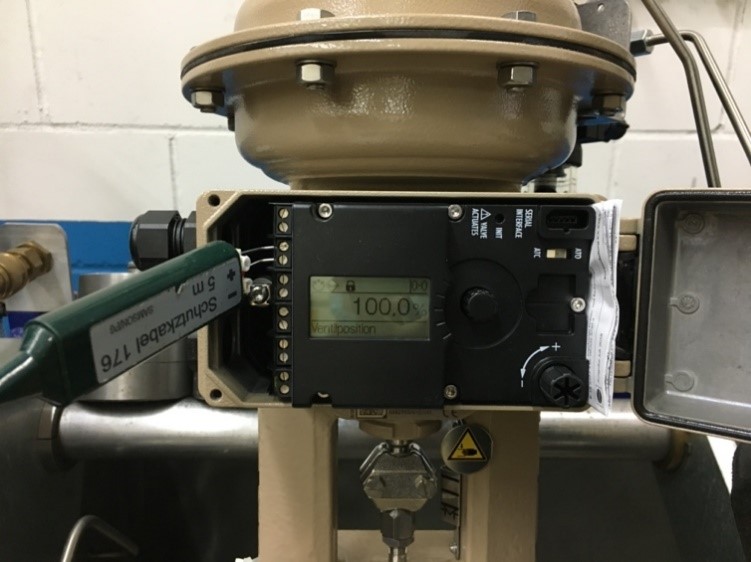
2. Positioner: It is used to check that a suitable degree of opening is reached or not which overcomes the issues of wear and friction
3. Body: It contains modulating elements, globe, a plug, butterfly or ball.
4. Trim: Trim is one such part of the valve that comes directly in contact with the fluid. It consists of the seat, disc, plug, and stem
5. Bonnet: It provides a mounting for the guide and actuator and a medium for the stem to pass through. It is made of the centerpiece, packing, packing nut and guide. The packing acts as a fastener between the bonnet and stem. It helps to avoid any leakage
6. Electrical accessories
Actuator:
An actuator is the part of a valve assembly that responds to the output signal of the process controller, causing a mechanical motion to occur which, in turn, results in modification of fluid motion through the valve.
An actuator has to be able to perform two basic functions:
- To respond to an external signal and cause a valve to move accordingly and with correct selection, other functions can be integrated into this assembly, such as desired fail-safe actions.
- To provide support (if required) for accessories such as positioners, limit switches, solenoid valves and local controllers.
There are five basic forms of the valve actuator, as listed below:
- Digital
- Electric
- Hydraulic
- Solenoid
- Pneumatic
Positioner:
Probably the most significant accessory that can be used for valve control is the positioner, sometimes referred to as ‘smart valve electronics’ many of which are microprocessor controlled.
A positioner is a high gain proportional controller which measures the stem position, within 0.1 mm, compares this position to a setpoint, which should be considered as the output of the main process controller, and performs correction on any resultant error signal. The open-loop gain of these positioners ranges from 10 to 200 giving a proportional band between 10 and 0.5% and their periods of oscillation ranges from 0.3 to 10 s, a frequency response of 3-0.1 Hz. In other words, it is a very sensitive tuned proportional-only controller.
In case of air operated valve, two control actions are possible:
- Air or current to close: Increment of flow restriction as to the control signal value increases.
- Air or current to open: Decrement of flow restriction as to the control signal value increases.
Failure to safety mode can also take place
- Air or control signal failure to open: On the failure of compressed air to the actuator, under the backup power or by spring pressure the valve gets opened.
- Air or control signal failure to close: On the failure of compressed air to the actuator, under the backup power or by spring pressure the valve gets closed.
The operation of modes of failure is required by the failure to safety process control specification of plant. In case of delivering chemical, it may fail closed and for cooling water, it may fail open.
4- Visual and Dimensional Checks
a) Visual check
Visual check is carried out mostly as per MSS SP-55 (Quality Standards for Steel Castings for Valves, Flanges, Fittings and Other Piping Components – Visual Method for Evaluation of Surface Irregularities). Visually examine include checking such items as mentioned below:
- All accessible areas for scratches, rust, dirt, dents, chips or any other non-design aspect which detracts from physical appearance and may be suggestive of poor quality.
- All painted surfaces for scratches, orange peel effect and drip
- Compliance to the Bill of Material items to be checked include but are not limited to:
- Model, Size, Rating, end connection, Serial Number, Material, Flow Direction
- Actuator and actuator mounting, Actuator fail direction, Handwheel, Rated Travel, air supply pressure
- Air set type, Positioner type, configuration and signal, Accessories, Accessory Mounting, Instrument certification, piping size & material and fittings.
- Serial plate data and the data on any other attached tags or plates.
- End connection and sealing surfaces to be free from damage.
- End connections to be protected against damage and corrosion (end cap, varnish or any other similar mean)
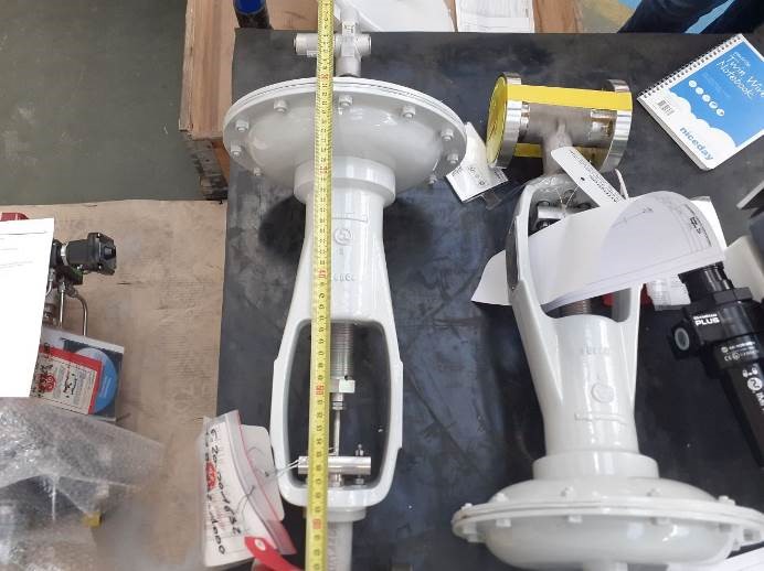
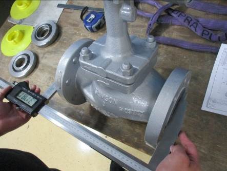
b) Dimensional check
The main dimensions including the connection flanges dimension such as face-to-face distance, total height, wall thickness, the diameter of holes, and the diameter in which holes were drilled are some of the most important dimensions which need to be checked completely. The measured dimensions need to be as per requirements and within the tolerances of the drawings and the below standards:
- Face-to-face dimensions as per ANSI/ISA-75.08.01, ANSI/ISA-75.08.06, and ASME B16.10.
- Flange facings and dimensions as per ASME B 16.5
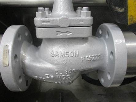
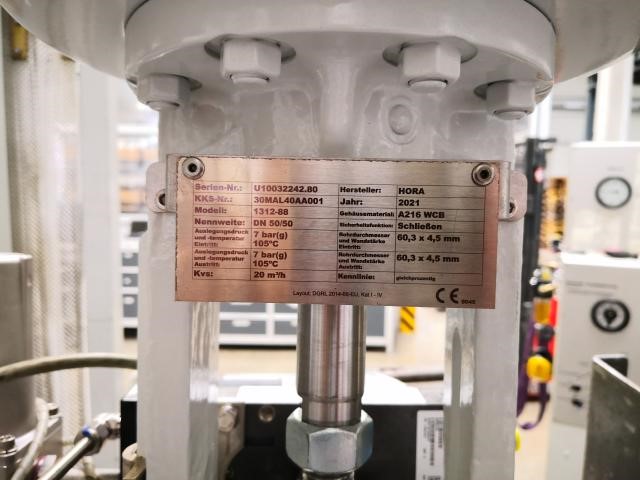
c) Marking Check
Valve name plate: Each valve shall have a non-corrosive nameplate permanently fastened to the place as specified in the reference drawings such as the actuator yoke. The nameplate shall be visible when the valve is in service and fully insulated. The nameplate shall include the following information:
- Manufacturer’s name or trademark
- Valve serial number
- Maximum valve body pressure rating
- Valve body material and body size
- Valve action and bench set
- Cv and characteristic
d) Metal Tagging
A stainless steel tag containing valve tag number and manufacturer’s serial number is usually and based on the client requirements attached or riveted to the valves. The inspector would check and confirm these numbers to the scope of supply (PO, BOM, etc.)
In the next part of this article, we will look at chemical analysis and pressure tests of control valves