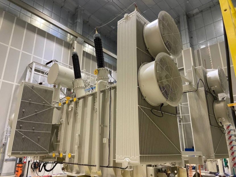
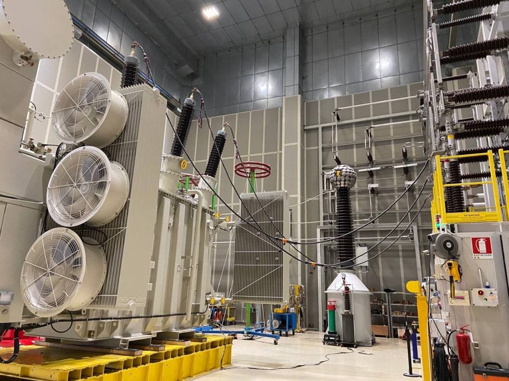
High-voltage transformers are some of the most important and expensive pieces of equipment required for operating a power system. The purchase, preparation, assembly, inspection, operation and maintenance of transformers represent a large expense to the power system. The third party inspection for power transformer including the witness of some inspection and tests is mandatory and cannot be waived and may require stringent monitoring and even assign resident inspector in manufacturing shop. Some others can be monitored and fully witnessing may not be necessary depending on the purchaser’s decision and how much they relay to the quality control system of the manufacturer. The IEC, NEC, NEMA, FDF, ISO ANSI, CI, IPCEA standard requirements normally are applied for inspection and test plans and procedures in the manufacturing shop.
Third Party Inspection for Power Transformer – OVERVIEW
There are a multitude of checks and tests performed as a transformer is being assembled at a substation. The test engineer may not directly perform all of the following tests and inspections but must be sure they are satisfactorily completed so that the final decision over transformer bank readiness for energization can be made. Some tests and procedures may be performed by specialists during the assembly phase. Special tests, other than those listed below, may also be required. Many require special equipment and expertise that construction electricians do not have and are not expected to provide.
Some tests are performed by an assembly crew, while other tests might be done by third party inspection for power transformer making the final electrical tests on the transformers. Physical size, voltage class, and kVA rating are the major factors that dictate the amount of preparation required to put transformers in service. Size and kVA rating also dictate the kind and number of auxiliary devices a transformer will require. All of these factors affect the amount of testing necessary to certify that a transformer is ready to be energized and placed in service.
The below tests and their descriptions are somewhat generically but apply to most transformers in one way or another.
- Physical Inspection
- Nameplate Data
- Auxiliary Components and Wire Checks
- Hand Meggering
- CT Tests
- Bushing Power Factoring
- Transformer Power Factoring
- Voltage Ratio, Polarity and Impedance
- Transformer-Turns Ratio
- Tap Changers
- Zero Sequence
- Winding Resistance
- Power Meggering
- Lightning Arrestors
- Temperature Devices
- Auxiliary Power
- Automatic Transfer Switch
- Cooling System
- Bushing Potential Device
- Auxiliary-Equipment Protection and Alarms
- Overall Loading
- Trip Checks
1. Physical Inspection
When transformers are received from the factory or reallocated from another location it is necessary to verify that each transformer is dry, no damage has occurred during shipping, internal connections have not been loosened, the transformer’s ratio, polarity, and impedance agree with its nameplate, its major insulation structure is intact, wiring insulation has not been bridged, and the transformer is ready for service. Physical inspection requires staff experienced in these techniques.
- To check:
- Oil leaks
- Oil pumps
- Fans and radiators
- Age
- To perform:
- Infrared temperature analysis for
- transformer tanks
- surge arresters
- bushings
- radiator and cooling systems
- Corona scope scan
- Infrared temperature analysis for
- Physical inspections of the following:
- Winding temperature indicators
- Pressure relief devices
- Sudden pressure relay
- Conservator bladder
- Conservator breather
- Bladder failure relay
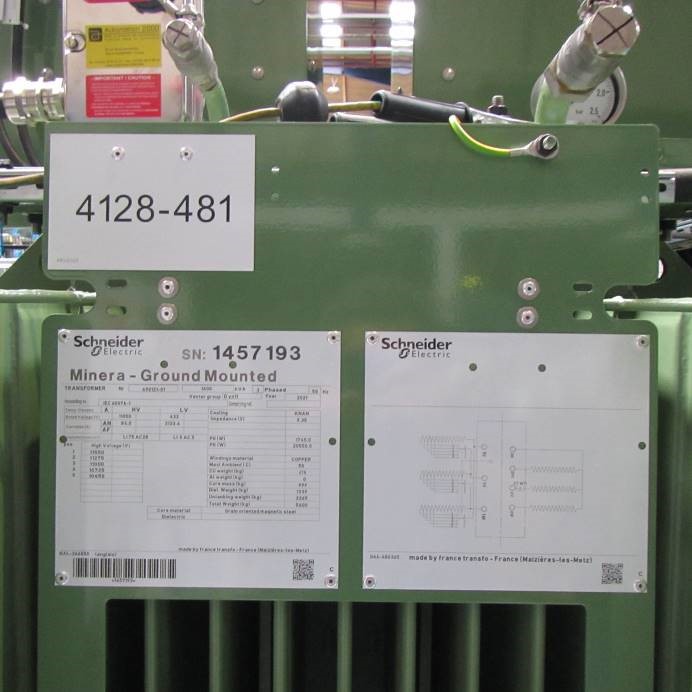
2. NAMEPLATE DATA and TERMINAL MARKINGS
Collecting nameplate data must be done for all equipment. This data is recorded by the person(s) performing the equipment tests. The act of recording the nameplate data also helps test personnel familiarize themselves with the unit to be tested. For a transformer, much of the needed information can be obtained from the main nameplate. If there is an under-load tap changer, it too will have a nameplate. CTs have nameplates and may have them on the bushing pockets where they are mounted with additional information on a nameplate placed inside the cooler-control cabinet door (typical on large transformers). Bushings, fuses, fan and pump motors, lightning arrestors, and disconnect switches will also have individual nameplates.
Terminal marking of power transformers is determined by ANSI standards. Two-winding transformers have terminals designated by H and X (e.g., H1, H2, X1, X2,), where H is the higher voltage-rated winding and X is the lower-voltage winding. As viewed from the high-voltage side, the H1 bushing terminal will be located on the right. Three-or-more-winding transformers will have winding designation H, X, Y and Z, where H is the high-voltage winding (or, the highest kVA-rated winding in case windings have the same
voltage rating) and X, Y, and Z are for decreasing winding voltage ratings.
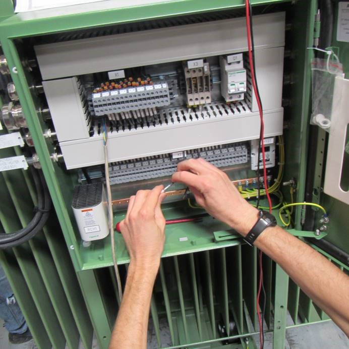
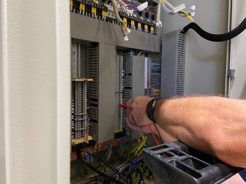
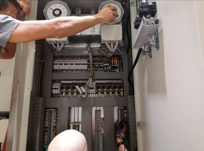
3. AUXILIARY COMPONENTS AND WIRE CHECKING
The size, type, and location of a transformer dictate the amount of external equipment associated with it. A transformer may be outfitted with devices that are not to be used at the time of installation. Even if not expected to be placed in service, all auxiliary equipment should be checked by a surveyor of third party inspection for power transformer in order for proper operation to assure it is not defective and could be utilized in the future if needed.
All wiring on the transformer should be checked and verified prior to energization. Control panels, terminal cabinets, and cables routed to the transformer should be checked. All screw, nut, and bolt terminals need to be torqued for tightness, including the wires on CTs where they originate at the connection boxes on the high-voltage bushings.
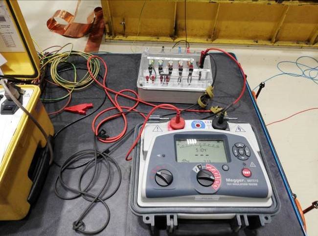
4. HAND MEGGERING (DC Hi-Potential Insulation Testing)
Most hand-crank Meggers have output voltages from 250 to 500 VDC. All wiring on transformers should be Meggered at 250 or 500 VDC. Early completion of wire checking and low-voltage-component meggering is advisable, especially when large transformers are to be tested. Completion of these tasks up front is important because it allows the application of power to alarm and control circuits without the worry of causing damage. Having auxiliary power available helps facilitate operational checks, especially when UL tap changers need to be operated to perform various tests.
5. Third Party Inspection for Power Transformer: CT TESTS
During third party inspection for power transformer, transformer bushing CTs should be tested using the Current Ratio test method before the transformer has been completely assembled. CTs should be tested before they are mounted on the transformer. In some cases, CTs may have to be tested by connecting test leads to both ends of an installed bushing. This can be difficult! If the CTs are already mounted in the transformer, large (high-capacity) current-testing leads can be pulled through the CT centers before bushings have been inserted.
Occasionally it is not possible to perform a Current Ratio test. CT tap ratios can be verified by applying a voltage across the full CT winding – a Tap Voltage Ratio test – then measuring the voltage drop across each individual tap. This is a simple test to perform, and voltage ratios will be directly proportional to the CT turns ratio between taps.
This Tap Voltage Ratio test, however, should not be chosen as a substitute for a Current Ratio test. The voltage method should be regarded as the last alternative. Testing the equipment at the rated current offers more assurance that it will perform as expected when placed in service. The Current Ratio method reflects this philosophy; the Tap Voltage Ratio method does not. The Tap Voltage method cannot establish true orientation (polarity) of the installed CT, or test the primary to secondary current ratio, and leaves some points unverified.
6. BUSHING POWER FACTORING (AC Hi-Potential Insulation Testing)
All bushings should be power factored before they are inserted into the transformer. If a Power Factor set is not available when a new transformer is being assembled, a capacitance bridge should, at the very least, be used to measure the bushing tap capacitance values. Measure the values for both C1 and C2 (especially if they are specified on the bushing nameplate). A proper capacitance test could indicate whether a serious internal problem with a bushing exists prior to insertion and whether a power factor test would be advisable.
7. TRANSFORMER POWER FACTORING (AC Hi-Potential Insulation Testing)
The transformer itself should be power factored in soon after the drying process is complete and the tank is filled with oil. All bushings should again be power factored at this time because their readings will change slightly after assembly. A complete set of Power Factor data should include winding-to-winding, winding-to-ground, and bushing tests. If a 10-kV power factor set is available, a Winding Excitation test should be performed. A Winding Excitation test on very large transformers may not be possible due to
insufficient capacity of the Power Factor set for supplying required excitation current.
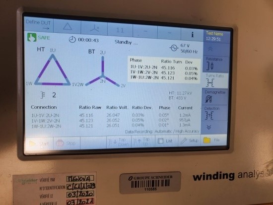
8. SINGLE-PHASE VOLTAGE RATIO, POLARITY and IMPEDANCE MEASUREMENTS
The third party inspection surveyor compares ratio, polarity, and impedance measurements are compared with nameplate data to verify their correctness and to ensure that there is no hidden shipping damage, that the transformer field assembly is correct, and that the transformer is ready for service. In addition, these test data reports become a valuable tool when compared with later diagnostic tests used to assess transformer conditions.
Single-phase test procedures can be used to measure the ratio and impedance of two-winding transformers, three-winding transformers, autotransformers, and three-phase transformers. Moreover, in the case of three-phase transformers (with a Wye connection) and grounding banks, zero-sequence impedance measurements are made with the single-phase procedure. Comparisons between measurements are useful when single-phase tests are made on three identical transformers or each phase of a three-phase transformer, as it is unlikely that each single-phase unit or each phase of a three-phase transformer would have sustained the same damage.
THREE-PHASE IMPEDANCE MEASUREMENTS
Impedance in percent (% Z) measured from the primary side, in theory, should equal the % Z measured from the secondary side. Impedance values calculated from the test data should compare closely to the % Z values shown on the manufacturer’s nameplate. However, because of coil size and spacings, winding connections, and three-core legs, leakage flux may not correspond for each measurement direction. Consequently, percent impedances may differ slightly. On a 9.0%-impedance (% Z) transformer, one should expect values to be in the range of 8.8% to 9.2%. For impedance measurements (as well as for ratio and polarity), one pair of test wires must be used to supply the test current and another pair to measure the voltage applied to the transformer. A significant voltage drop can occur across the test leads supplying current; thus, the exciting voltage must be measured directly at the transformer terminals.
9. VOLTAGE RATIO AND POLARITY MEASUREMENTS ON TWO-PHASE OR THREE-PHASE TRANSFORMERS
Methodology of third party inspection for power transformer Voltage Ratio and Polarity measurements is the same for single-phase as for two- and three-phase machines. The polarity of the windings is easily checked at the same time the voltage ratio is being tested. The important concern when performing a polarity check is to tie the non-polarity ends of the two separate windings together and measure across the polarity ends. The resultant voltage will either be the sum or difference of the two separate winding voltages, a sum indicating additive and a difference indicating subtractive polarity. Transformers above 500 kVA are built with subtractive polarity.
10. TAP CHANGERS
Tap changers allow transformer input and output voltages to be matched with the rest of the power system or to adjust voltage levels between power sources and customers. They allow transformers to be applied in situations where voltage control would be very difficult without utilizing additional expensive equipment.
When a no load (NL) tap changer is tested, a small amount of current is applied to excite the tap winding, and a meter monitoring the output winding is carefully observed to determine where windings are dropped out and picked up during tap changes. This check should be used to verify that tap-changer contacts are properly centered and that they do open and makeup at the correct point between tap changes.
When testing under load (UL) tap changers, the excitation current should be monitored continuously to verify that the winding is NEVER open-circuited. Both local and remote operation and indication of UL tap changers must be verified. Remote operation from the control house should be tested completely. The limits of the control should be checked to see that the tap changer will not go beyond its stops.
11. THREE-PHASE THREE-WINDING TRANSFORMERS
Single-phase tests of ratio, impedance and zero sequence of three-phase three-winding transformers, if all phase terminals are available, are made between corresponding winding-pairs that are on the same core leg. For example, High to Low (H to L), High to Tertiary (H to T), and Low to Tertiary (L to T). In each of these cases, there will be a single-phase procedure in Section 8.12 that will apply.
The three-phase three-winding transformer with a buried delta, in which the delta-phase terminals are not brought out to bushings and one corner of the delta is made up by a link, will require special test procedures.
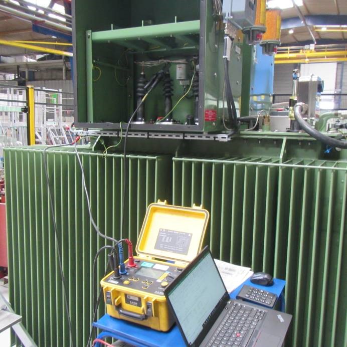
12. TRANSFORMER WINDING DC RESISTANCE MEASUREMENT
DC Winding Resistance tests serve as another assurance measure of third party inspection for power transformer that no loose connections, discontinuities, or problems exist with the internal portion of the transformer and that shipping has not loosened lead connections inside the bank. Field measurements of transformer winding resistance are used initially to compare with factory data for verifying the “as-received” winding taps, lead, and link connection tightness; to determine average winding temperature, before and after a heat run; and in later life, if the transformer has electrical problems, as a diagnostic tool to determine the condition of the transformer taps and winding connections. Correlation with factory data and use as a benchmark for future diagnostic tests require accurate, repeatable winding resistance measurements and accurate measurement of winding temperature.
13. TRANSFORMER POWER MEGGERING (Insulation Evaluation Using Hi-Potential DC)
The insulation level of transformers should be tested with a regular power Megger with 2500-VDC capability. A test voltage of 2500-VDC needs to be applied from winding-to-winding for all combinations, and winding-to-ground for all windings. Windings (or bushings)-to-CTs are tested at 2500 V as well. The Megger output should be switched to the 500-V scale and CT secondaries to be tested to the ground and between other CTs. The 500-V Megger output should be used for any test involving low insulation levels such as found on the bushing taps of some smaller bushings. High-voltage underground cables for connecting the power transformer to the power system should be meggered at 2500 V.
14. LIGHTNING ARRESTORS
Lightning arrestors are used to protect equipment from lightning strikes and high-impulse switching surges. Because of the relatively low Basic Insulation Level (BIL) of a transformer, a lightning arrestor should be installed to protect every transformer bushing connected to a line or a high-voltage bus. A lightning strike or switching surge initiating an arc-over inside a costly transformer is clearly undesirable.
Within third party inspection for power transformer, each arrestor and each individual section of stacked arrestors should be Meggered at 2500 VDC. The nameplate kV rating for each arrestor should be verified to be sure it is the proper size for the application. Also, the installation and connection of proper hardware, e.g. grading rings for arrestors 115 kV and above, standoff insulators for all 500-kV and some 230-kV arrestors, and ground conductor should be verified.
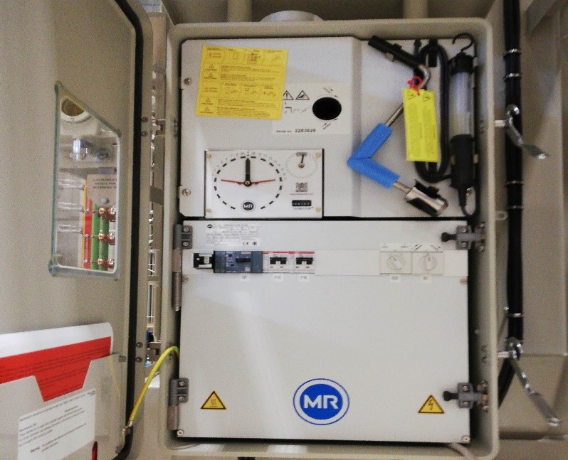
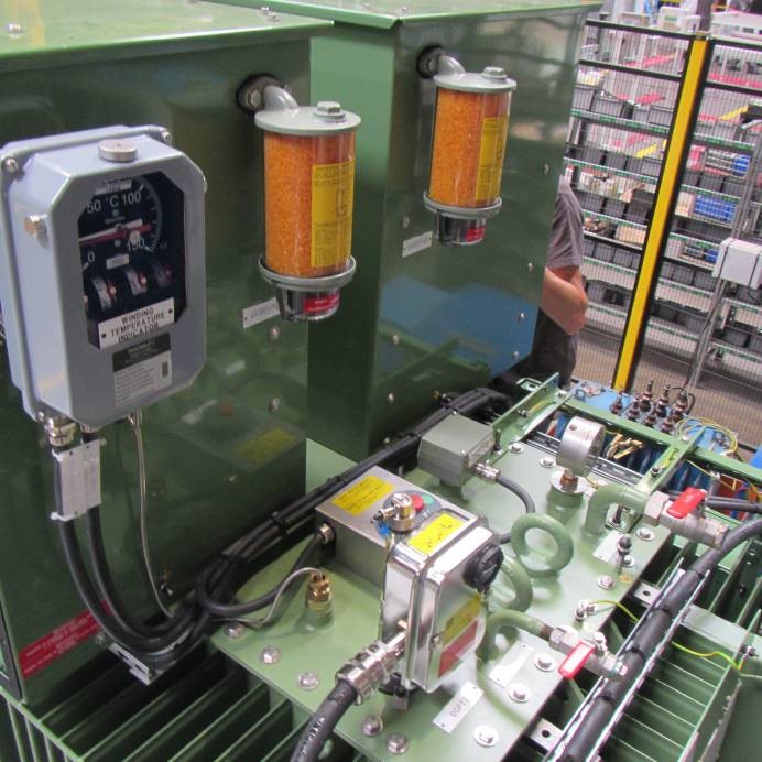
15. TEMPERATURE DEVICES
All large transformers have a temperature-indicating device of some type, and most have temperature recorders as well. An indication may be for top-oil temperature or hotspot temperature. Additional temperature-sensing equipment may be installed to provide alarm and control signals needed to activate automatic cooling systems. Indicator operation may be purely mechanical (tank-mounted temperature gauge or thermometer), purely electrical (SCADA transducer & some chart recorders), or a
combination of the two (chart recorder & multipoint temp recorder).
Temperature indicators, recorders, and controls must be functionally checked and have their calibration verified. The most common method used for calibrating these devices is to immerse all heat sensor detector bulbs in a container of oil, then heat the oil at a slow, constant rate. The oil-temperature changes are measured with a temperature standard (thermometer), and readings for all devices immersed in the oil are recorded simultaneously.
16. AUXILIARY POWER
Transformers that require continuous or cycled forced air and/or oil cooling systems to maintain safe operating temperatures require an external power source. Cooling system power may be provided from the station service supply, at the substation, or by a customer source. More than one power source is required to provide cooling system backup for the loss of main source power. Some installations have auxiliary or station-service transformers dedicated to obtaining cooling power from local sources that are not directly compatible. These small transformers, used for cooling-system power, should also be tested.
17. AUTOMATIC TRANSFER SWITCHES
Transformers that require continuous cooling by auxiliary pumps and fans must be supported by two independent power sources to ensure transformer service when the primary source fails. Many large transformers are rated for an operating time of one hour or less without having their cooling fans and pumps in operation. When two power sources are provided to feed one critical circuit, an automatic transfer switch is usually provided and may have controls at the transformer.
Automatic transfer switches often have alarm and indication points that should be verified to be in working order. As with all electrical components of a power system, wiring and functional operation of these switches must be checked. This includes a check for proper phase rotation of three-phase sources and ties. A phase-rotation check must be made for all power sources feeding the transfer switch. Fans and pumps don’t provide cooling if operating in reverse. Proper operation of the transfer switch should be observed by killing the source voltages, then re-energizing them in various sequences to assure that everything functions as expected.
18. COOLING SYSTEM
Setting and testing the control devices of the cooling system equipment for proper operation ensures reliable operation and long service life for transformers. The long-term operation of transformer cooling systems is usually quite stable and trouble-free if the cooler controls have been checked and set properly. It is easiest to “work out the bugs” during the initial installation and testing of a transformer because there is basically unrestricted access for manipulation of cooling controls. Standard wiring and component checks, terminal tightening, verifying and Meggering should be performed prior to applying control power. As soon as the operating controls can be powered up, all manual and automatic control
functions should be verified.
19. BUSHING-POTENTIAL DEVICES
Potential devices may be mounted on transformer bushings where the accuracy of voltage transformers is not required and where the installation of VTs would not be cost-effective. Point-to-point wiring, torque of screws and terminal tightness, and meggering of insulation are required checks. The high-voltage probe that supplies the bushing tap voltage to the potential device should be meggered at 2500 VDC.
20. AUXILIARY PROTECTION EQUIPMENT
Various types of auxiliary alarm, indication, and protection equipment are also found on transformers. The amount and type of auxiliary equipment provided depend on the size of, and who manufactured the transformer.
Pressure relief is necessary for all transformer main tanks and UL tap-changer tanks. Each tank is completely separate and has its own relief. Pressure reliefs are usually outfitted with mechanically operated lever arms and can be manually tripped and reset to verify proper alarm contact operation.
Oil-level indicators are provided on nearly every type of oil-insulated electrical equipment (transformers included). The oil level should be checked for every tank and every bushing on the transformer before energization. Functional operation of transformer main-tank and tap-changer oil-level indicating devices must be checked before the units have been filled with oil.
21. OVERALL LOADING
CT circuits for transformers should be loaded overall before the transformer is placed in service. For an assembled transformer, injection of high current into the CT primary for purposes of overall loading is impossible with the available test equipment. A simulated current is needed to be injected at the cable termination point for each CT secondary in the individual transformer terminal cabinet. A return path is needed for this injected current from the insertion points of the control house relays, so that magnitude and polarity can be verified. Spare cable wires are usually available for this purpose, which typically requires two people.
22. TRIP CHECKS
Trip checks verify that a transformer can be removed from service for various kinds of trouble. Verifying the trip function may be critical to the longevity of a transformer. Checks from devices that monitor slow-developing problems, that do not require immediately removing a transformer from service (such as overheating due to loss of cooling), may not seem critical, but they are. Even though a considerable time delay is allowable, the service life of a transformer would be reduced if it didn’t eventually trip. For severe internal problems, such as a flashover or fault within the windings, instantaneous de-energization of the transformer is imperative to prevent irreparable damage and possible explosion or fire. For this reason, special relays are often used with the larger transformers to provide the fastest means of fault detection available to clear the faulted equipment from service.