INTRODUCTION
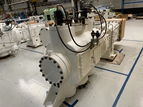
Reciprocating compressors should be considered the mother of all compressors today. These compressors function very similarly to car combustion chambers; With the difference is that at the moment of compression of the fluid, there is no more spark and explosion and the compressed gas must be directed outwards from the outlet valve. Check reciprocating compressors, they can be examined in separate sections. Compression in a reciprocating compressor is done by moving the pistons back and forth inside the cylinder.
The number of these pistons determines the capacity of the compressor and increases it. The reciprocating motion of the pistons is linear. But the driving force behind this linear motion is a crankshaft that rotates. The crankshaft is moved by the motor of the device and goes through a circular motion in a row. On the other hand, each piston is connected to the crankshaft with the help of connecting rods. In this way, the rotational movement of the crankshaft is converted into linear and reciprocating motion of the pistons, and suction, compression, and discharge operations are performed in piston compressors.
The purpose of compressors is to move air and other gases from place to place. Gases, unlike liquids, are compressible and require compression devices, which although similar to pumps, operate on somewhat different principles. Compressors, blowers, and fans are such compression devices.
The purpose of compressors is to move air and other gases from place to place. Gases, unlike liquids, are compressible and require compression devices, which although similar to pumps, operate on somewhat different principles. Compressors, blowers, and fans are such compression devices.
- Compressors. Move air or gas in higher differential pressure ranges from 35 psi to as high as 65,000 psi in extreme cases.
- Blowers. Move large volumes of air or gas at pressures up to 50 pounds per square inch.
- Fans. Move air or gas at a sufficient pressure to overcome static forces. Discharge pressures range from a few inches of water to about / pound per square inch.
Scope:
This content guides inspectors through all the necessary stages in the production of the reciprocating compressors, including the examination of material, casing hydrostatic testing, performance test, mechanical run test, final inspection.
In general, reciprocating compressor components can be divided into three categories: fixed components, moving components, and peripherals.
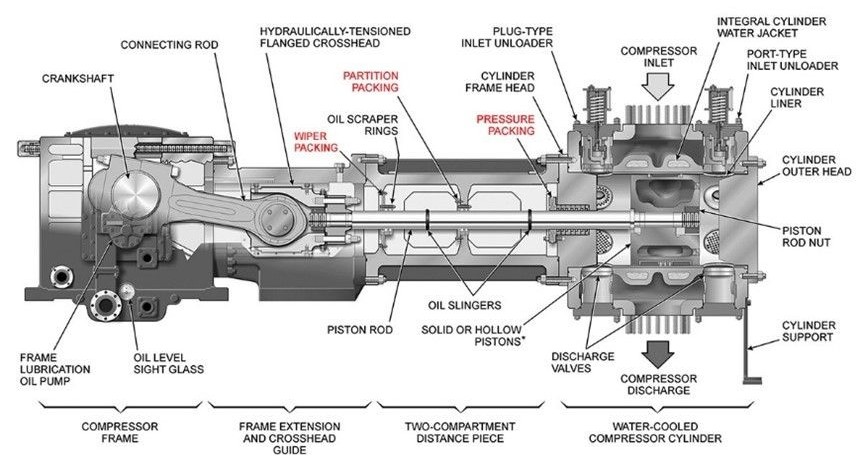
Stationary Components of a reciprocating compressor
- Cylinder
- Valve
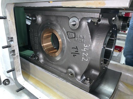
- Crank Shaft Box
- Piston Ring
- Bearing
- Packing
- Stuffing Box
Moving Components
- Piston
- Piston Rod
- Connecting Rod
- Crosshead
- Flywheel
- Crank Shaft
Auxiliary Components of a reciprocating compressor
- Driver
- Gear Box
- Cooler
- Pulsation Dampener
- Recycle Valve
Required Documents for Review:
The list of documents normally is agreed upon in the Pre-Inspection meeting, which is held several weeks before the actual commencement of the inspection work.
- Purchase Order or Contract
- Vendor Quality Plan
- WPS & PQR
- Welding Procedures
- NDT Procedures
- WQT Qualification Reports
- Hydrostatic Procedures
- Performance Procedures
- Painting Procedures
- Calibration Certificate of Used Equipment
- Water Quality Analysis
- Packing and Shipping Procedures
Fabrication Inspection
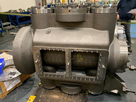
Casting (Material Inspection)
The first actual inspection work in the reciprocating compressor is the raw materials inspection such as Review of 3.1 material certificates such as Chemical analysis, Heat treatment, stress relief, Mechanical properties.
- NDE: MT, UT & VT
- Oil whiting test (Leak test bottom frame)
Machining
- Stress relief heat treatment after pre-machining and before final machining
- NDE: MT, UT & VT
- Final visual examination and dimensional inspection.
Bar over test
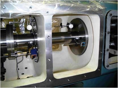
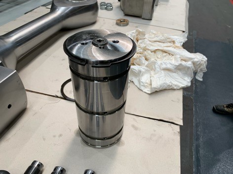
Reciprocating compressor bar-over test includes measurements of piston end clearance and piston rod vertical and horizontal runout measurement.
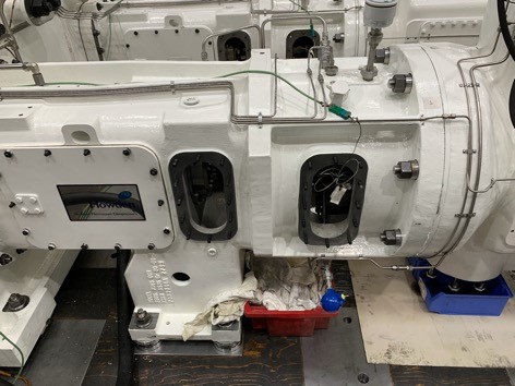
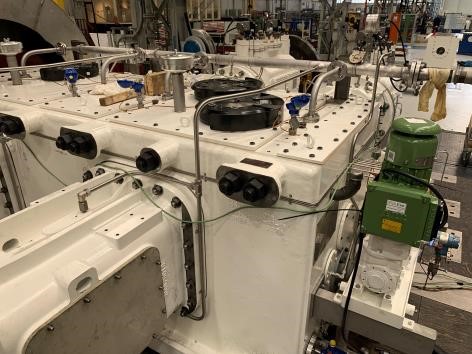
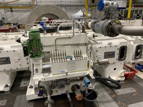
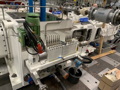
Mechanical Running Test
The mechanical running test is executed for four hours on the compressor. During the mechanical running test, speed, oil differential pressure over the filter, oil temperature aftercooler, oil flow to compressor header, and temperature of the stuffing box is recorded.
- The rotating speed of the compressor shall be measured by the tachometer every 30 minutes. The measurement value is an average value of those indicated by the tachometer. Rotating speed was within +5% of the specified rotating speed.
- The supplied oil temperature and discharged oil temperature of the crankcase shall be measured with the temperature gauges in the lube oil unit every 30 minutes. The supplied oil temperature and the discharged oil temperature should not exceed 65ºC.
- The supplied oil pressure to the crankcase (bearings) and the discharge oil pressure of the lube oil pump shall be measured with pressure gauges in the lube oil unit every 30 minutes. The measurement value of bearing supply pressure is within the pressure specified in the datasheet.
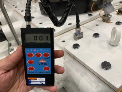
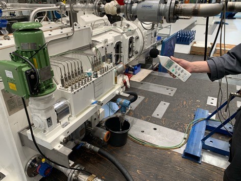
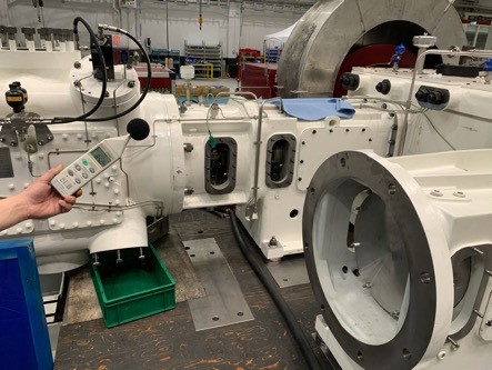
- The crankcase vibration is measured on a real-time basis in X and Y axises. The cylinder vibration is measured in X, Y, and Z axises (Horizontal, Vertical, and Axial). The measured values shall be verified against the acceptance criteria provided in API 618 or the approved test procedure.
- The noise level shall be measured at the rated speed and the measurement is taken at approximately 1,5 meters above ground level and approximately 1 meter far from the compressor.
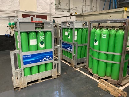
Helium/ Nitrogen leakage test
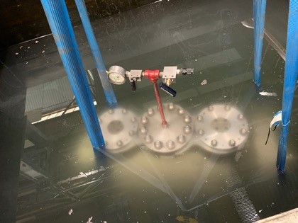
Cylinders are filled with 5% Helium and 95% Nitrogen as the test medium. The Helium/ Nitrogen leakage test of each cylinder, cylinder head end cover, and valve covers are performed at the same time and pressure according to the Mechanical running test procedure.
Cylinders are pressurized up to the test pressure and submerged in the water. The holding time of 1 hour is considered as per the mechanical running test procedure. The pressure is monitored during the test. The test pressure is stable during the test time. No leaks, pressure drops, bubble formation, damage, and deformation is observed during the test. The cylinder’s pressure-retaining parts are depressurized after the test.
Performance Test
The reciprocating compressor aerodynamic performance testing is not a routine test in the reciprocating compressor testing and is identified as an optional test in API 618. If the performance test was a purchase order requirement, then is performed based on ISO 1217 and with cylinder valves installed in the closed loop system.
The efficiency value shall not be less than the specified value. The power consumption also shall be checked not to be more than 3% of the rated value.
After running test: After running test: parts to be dismantled for inspection
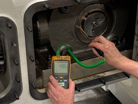
Immediately after the test, the temperatures of main bearings, connecting rod bearings, cross head bearings, and piston rods are measured and the values must be in accordance with the acceptance criteria noted in the Mechanical running test.
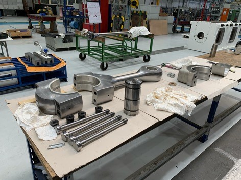
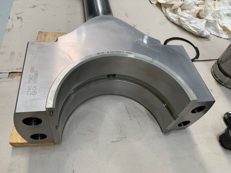
Final Inspections include visual and dimensional check
After the mechanical running test, one cylinder assembly of the compressor is dismantled and the following items must be checked and the visual inspection of dismantled parts of the compressor must have no deformations, scratches, and damages on the main bearing, crankpin bearing, crosshead pin bearing, cylinder liner, piston, and piston rod. Main dimensions according to the drawings.
The following components are used from Job equipment
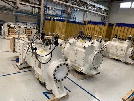
- Compressor main unit
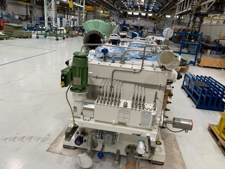
- Lube oil unit
The following components are used from the test stand
- Motor
- Pressure gauge
- Temperature gauge
The following components are not used in the test
- Suction/Discharge Valves
- Surge Drum
- Gas Piping
- Drum/Piping Support
- Instrument
Activity: testing of the separate lubricating oil system
- Completeness check
- Flushing
- Running test
- Final inspection (Final visual and dimensional inspection)
Final inspection includes nameplate check and paint inspection
- The inspector must check the content in accordance with the approved drawings and specifications and stamp in accordance with the drawing and specifications.
- The inspector must surface for painting is checked for the DFT and surface preparation and ral code, and adhesion test according to specification.
Thanks for writing a blog on the reciprocating compressor. I agree that a reciprocating compressor is a vital product in manufacturing industries.