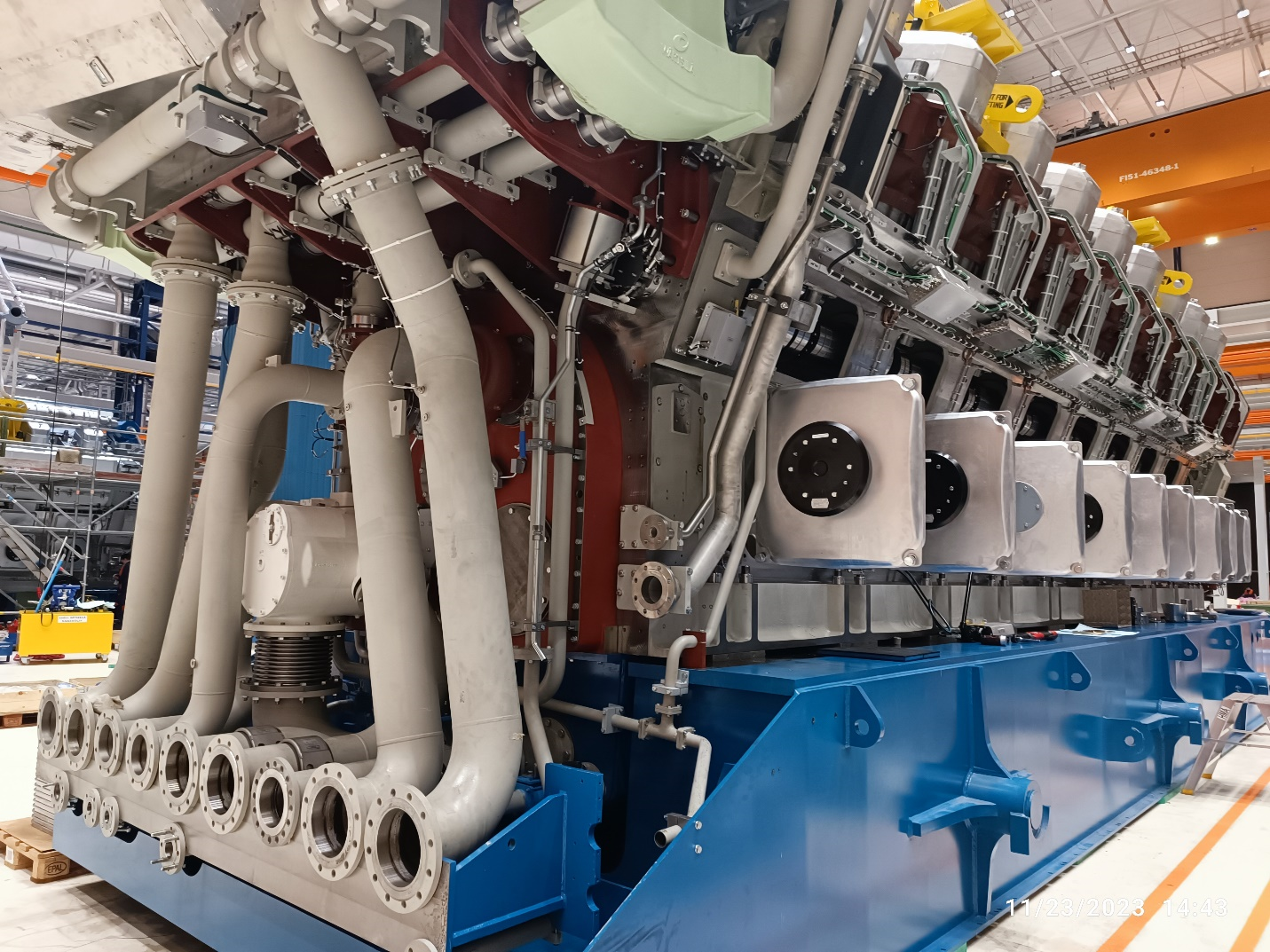
There are various parts in compressor systems and so many tests could be carried out to control the quality according to the order specification and related reference standards and codes.In this article, “Centrifugal compressor testing” some critical tests will be described, which are generally applied on most of the centrifugal compressors in the oil and gas and petrochemical industries.
In the previous article “TPI inspection for Centrifugal Compressor,” some activities were mentioned, which are inspected by a third party inspection representative on the compressor casing, bearing, shaft-rotor.
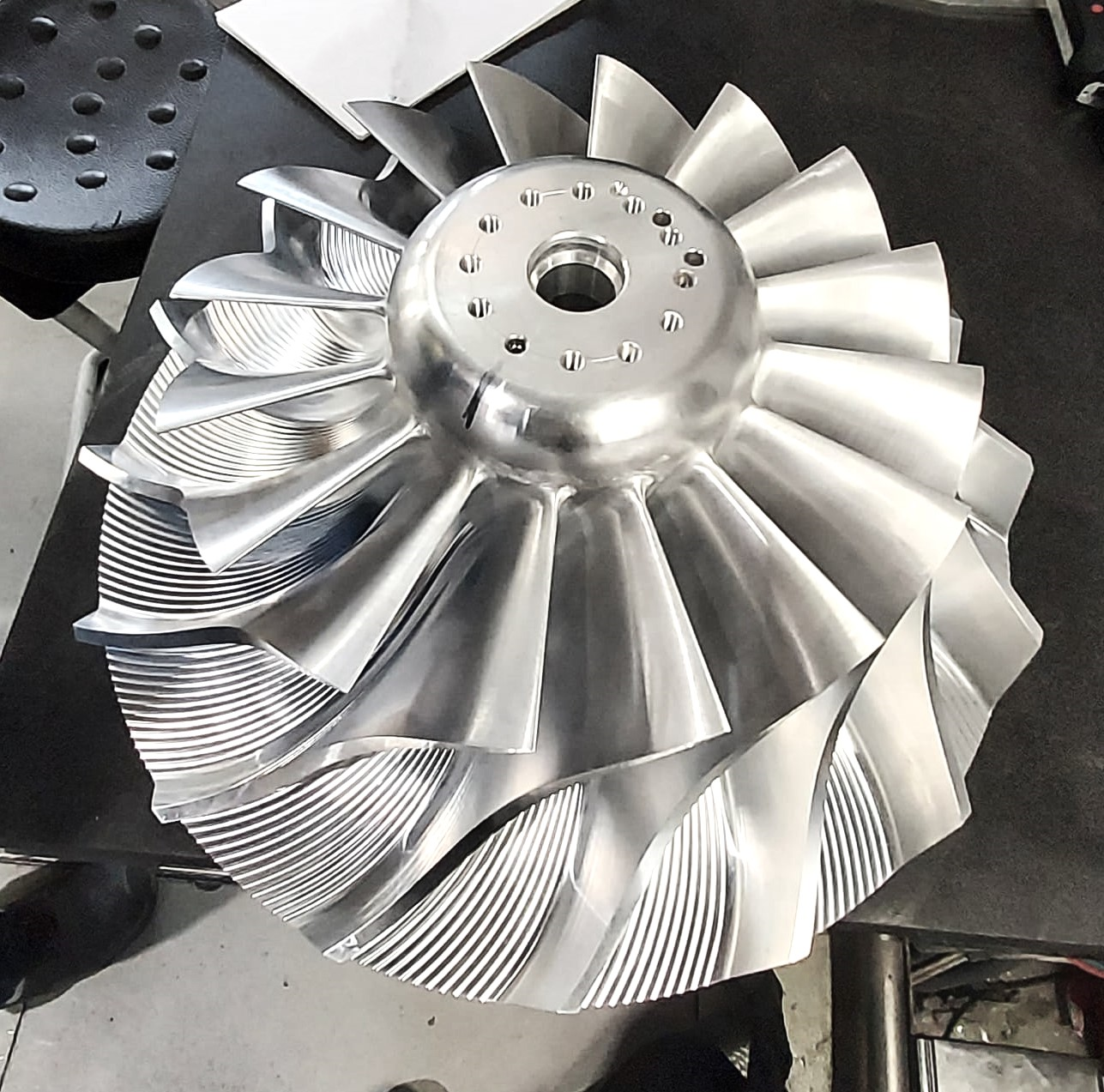
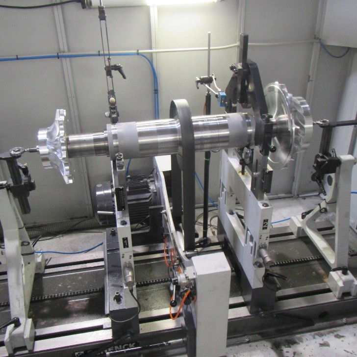
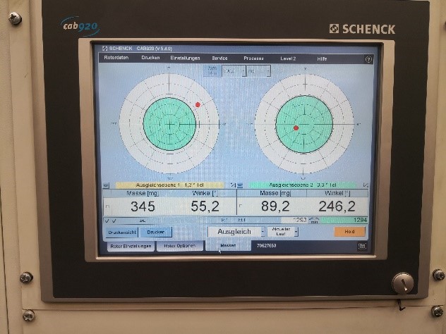
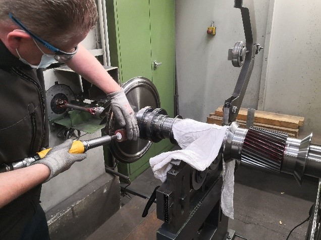
1- High-speed balancing of the complete rotor assembly:
Dynamic balancing of the rotating element is a critical step of compressor production, which is tested under the presence of the third-party inspection representative to achieve acceptable results. Each unbalancing can cause major operational problems and also internal damage to the centrifugal compressor. Therefore, the balancing should be checked accurately based on the acceptance criteria and acceptance limit of the reference documents to prevent any consequential damages and reduce the maintenance costs.
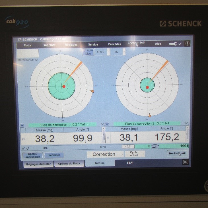
2- Residual unbalance response verification test:
After the high-speed balancing test of the assembled rotor, no residual unbalancing should be detected, therefore if any out-of-range unbalancing is observed, it should be repaired by needful corrective action and finally, this step should be verified for further steps.
The location of the unbalancing is specified in the balancing test by the manufacturer.
3- Centrifugal Compressor Testing- PMI:
The technical inspector witnesses the PMI test on the shaft rotor and compare the results with the material reference code/standard or technical ordered specification and report them to the customer.
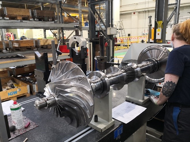
4- What is Mechanical and electrical runout?
Mechanical Runout is one of the important steps of “Centrifugal compressor testing”, which is performed to measure the shaft’s deviation from a perfectly uniform radius as its circumference is traversed. This type of runout is detected by a dial indicator.
4.1. How the vibration probe applied on the runout test?
Electrical and mechanical runout shall be determined by rotating the rotor through the full 360 degrees supported in V blocks at the journal centers while continuously recording the combined runout with a non-contacting vibration probe and measuring the mechanical runout with a dial indicator at the centerline of each probe location and one probe-tip diameter to either side.
The radial-vibration probes sense the rotor shaft to be concentric with the bearing journals. All shaft sensing areas (both radial vibration and axial position) should be checked to be free from stencil or scribe marks or any other surface discontinuity for a minimum of one probe tip diameter on each side of the probe.
These areas shall not be metalized or plated except vendors with proven experience or test data may metalize shafts to reduce electrical runout.
By means of eddy current proximity probes, the roundness of the shaft is measured through a function of the electrical conductivity and magnetic permeability of the target material. The physical out of roundness results of the rotating shaft is evaluated and compared with the acceptance limits, which are specified in the test procedure and reference documents.
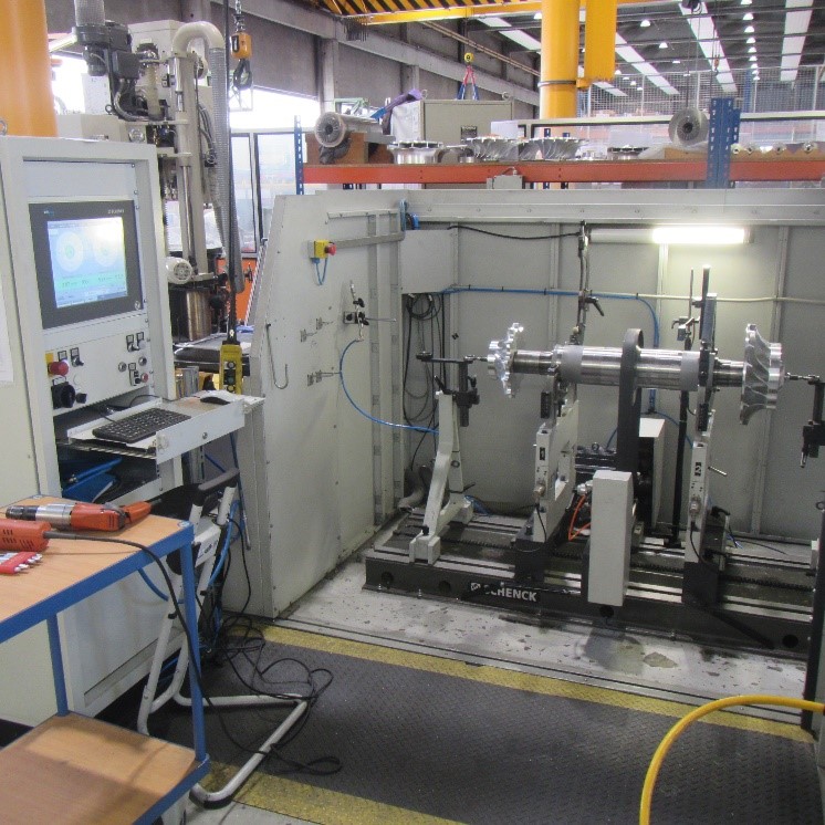
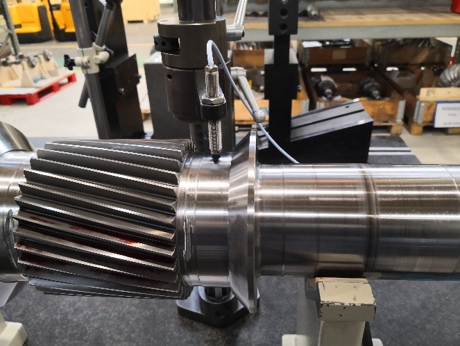
During the mechanical running test, the amplitude and phase angle of the shaft vibration from zero to trip speed shall be recorded. The location of the critical speed below the trip speed is established. Probes are mounted on both sides of gear teeth close to bearings.
4.2. How the runout test is done?
The amplitudes and phase angle of the shaft vibration are recorded during the mechanical running test from zero to trip speed.
The gain of any analog recording instruments used shall be preset before the test so that the highest response peak is within 60% – 100% of the recorder’s full scale on the test unit coast-down (deceleration).
During the mechanical running test of the machine, assembled with the balanced rotor, operating at its maximum continuous speed or any other speed within the specified operation speed range, the peak-to-peak amplitude of unfiltered vibration in any plane, measured on the shaft adjacent and relative to each radial bearing, should be in the specified range in the standard.
The operator turns the shaft package and the probe detects the surface profile on the shaft, data is sent to the data acquisitions system in form of graphs.
In case of any deviation, corrective needful action should be done to achieve the acceptable result.
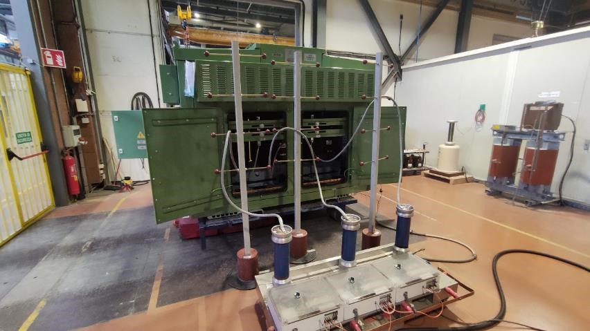
5- Centrifugal compressor testing- Demagnetization verification:
In the last step of finalizing the shaft-rotor, demagnetization verification should be done to be ensured no residual magnetic effect has existed from the previous testing.
In the next article “Centrifugal compressor inspection“, some additional tests related to the further steps will be described, which based on the inspection and test plan should be performed (either to be witnessed or to be reviewed) by third-party inspection.