Today, it is difficult to find a structure that does not use welding. There are several reasons for this, and perhaps one of the main ones is the economics of this bribe due to its higher connection rate. Welded joints, in addition to many advantages, also have disadvantages that need to be inspected and tested by qualified persons in order to ensure compliance with quality requirements is one of them. The need for welded joints for inspection and testing is due to the existence of discontinuities in the weld and the need for initial and in-service inspections of these discontinuities.
Welding defects
When we want to talk about welding defects, we must first determine what the technical definition of the defect is. A defect is a defect that, under general or predictable conditions, is likely to cause structural failure. A defect is actually a discontinuity that is not acceptable according to the code or technical specifications. Therefore, a specific discontinuity may be considered a defect in one structure and a defect in another. welding defects (Defects in the weld zone) may be two-dimensional (such as cracks) or three-dimensional welding defects (such as pores and cavities).
Two-dimensional welding defects are more dangerous and more difficult to detect and track. However, it should be borne in mind that both two-dimensional and three-dimensional welding defects cause stress concentration, which is important for dynamic loading. Excess pores or porosity also indicate a weak weld, which may have other more dangerous defects in addition to the pore.
Discontinuity:
An interruption of the typical structure of a material, such as a lack of homogeneity in its mechanical, metallurgical, or physical characteristics. A discontinuity is not necessarily a defect.
An undesirable discontinuity. A discontinuity or discontinuities that by nature or accumulated effect render a part or product unable to meet minimum applicable acceptance standards or specifications
AWS A3.0M/A3.0 : 2010
Defect:
A discontinuity or discontinuities that by nature or accumulated effect render a part or product unable to meet minimum applicable acceptance standards or specifications. The term designates reject ability.
AWS A3.0M/A3.0:2010
Aligned discontinuities:
Three or more discontinuities aligned approximately parallel to the weld axis, spaced sufficiently close together to be considered a single intermittent discontinuity.
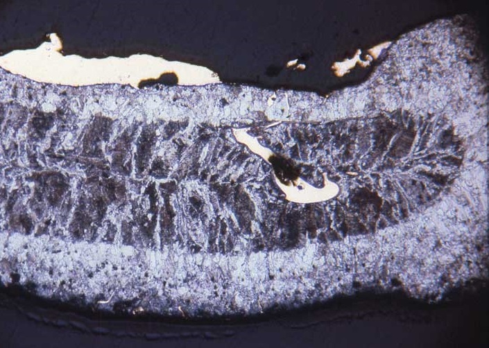
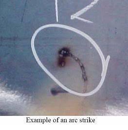
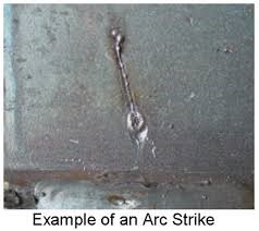
A discontinuity resulting from an arc, consisting of any localized remelted metal, heat-affected metal, or change in the surface profile of any metal object.
AWS A3.0M/A3.0:2010
A discontinuity consisting of any localized remelted metal, heat-affected metal, or change in the surface profile of any part of a weld or base metal resulting from an arc.
ASM Handbook, Welding, Brazing, Soldering, Vol.6
Coalescence:
The growing together or growth into one body of the materials being joined.
AWS A3.0M/A3.0:2010
Incomplete Coalescence:
A weld discontinuity in which complete joining of joint faying surfaces has not been achieved.
AWS A3.0M/A3.0:2010
A crack that develops after solidification is complete.
ASM Handbook, Welding, Brazing, Soldering, Vol.6
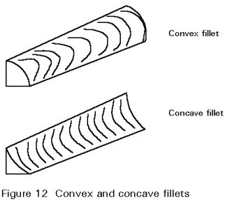
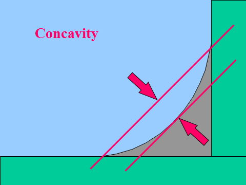
Concavity:
A weld extending continuously from one end of a joint to the other. Where the joint is essentially circular, it extends completely around the joint.
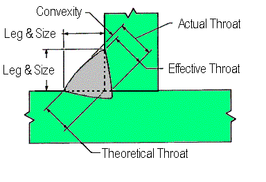
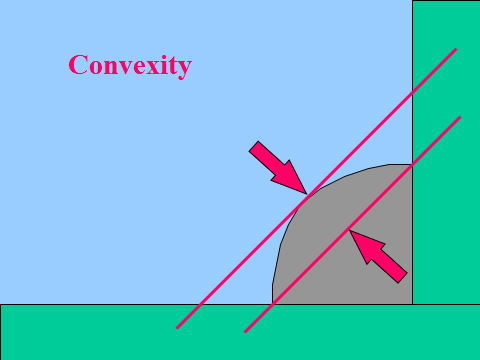
Convexity is the configuration present in fillet welds described as the maximum distance from the face of a convex fillet weld perpendicular to a line joining the weld toes
AWS B1.10
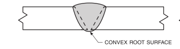
Convex root surface:
The configuration of a groove weld exhibiting root reinforcement at the root surface
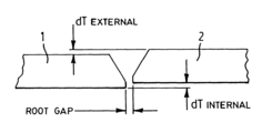
The amount a joint is out of alignment at the root
AWS D1.1
Misalignment :
The amount a joint is out of alignment at the root Parts to be joined at butt joints shall be carefully aligned. Where the parts are effectively restrained against bending due to eccentricity in alignment, the offset from the theoretical alignment shall not exceed 10% of the thickness of the thinner part joined, or 1/8 in. [3mm], whichever is smaller.
AWS D1.1
Arc Voltage :
The electrical potential between the electrode and workpiece.
AWS A3.0M/A3.0:2010
The voltage across the welding arc. Arc voltage is the total voltage between the electrode holder and the base metal immediately adjacent to the arc terminals.
Arc welder is another term for arc welding machine applied to a source of electric energy which produces welding currents within reasonable limits for use in arc welding.
A material or device placed against the backside of the joint adjacent to the joint root, or at both sides of a joint in electro slag and electro gas welding, to support and shield molten weld metal. The material may be partially fused or remain unfused during welding and may be either metal or nonmetal.
AWS A3.0M/A3.0:2010 & ASM Metals Hand Book Vol.6
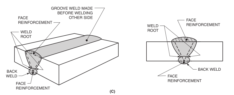
BACK WELD:
A weld is made at the back of a single groove weld.
The removal of weld metal and base metal from the weld root side of a welded joint to facilitate complete fusion and complete joint penetration upon subsequent welding from that side.
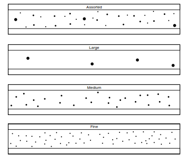
Porosity is defined as gas trapped by solidifying weld metal before the gas has a chance to rise to the surface of the molten puddle and escape. Individual or scattered porosity (P) shall be considered a defect should any of the following conditions exist: a. The size of an individual pore exceeds 1/8 in. (3 mm). b. The size of an individual pore exceeds 25% of the thinner of the nominal wall thicknesses joined. c. The distribution of scattered porosity exceeds the concentration permitted by Figures 19 or 20.
API 1104
Fusion zone:
The area of base metal melted as determined on the cross section of a weld.
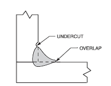
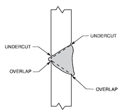
A groove melted into the base metal adjacent to the weld toe or weld root and left unfilled by weld metal.
ASM Metals Hand Book Vol.6
Welding:
A joining process producing coalescence of materials by heating them to the welding temperature, with or without the application of pressure or by the application of pressure alone, and with or without the use of filler metal.
A localized coalescence of metals or nonmetals is produced either by heating the materials to the welding temperature, with or without the application of pressure, or by the application of pressure alone and with or without the use of filler material.
are flat, generally elongated base metal discontinuities found in the central thickness area of wrought products.
AWS B1.10
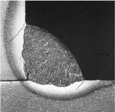
Delamination:
is the separation of a lamination under stress. The stresses may be generated by welding or may be externally applied. The separation of existing lamellar discontinuities may be found visually at the edges of pieces, or ultrasonically by testing with a straight beam search unit. A delamination discontinuity, like laminations, cannot transmit tensile loads perpendicular to the plane of delamination.
AWS B1.10:2010
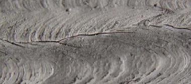
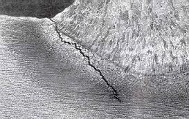
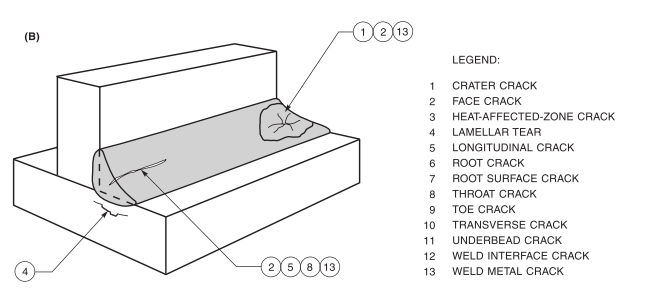
Lamellar tear :
are terrace-like fractures in the base metal with a basic orientation parallel to the wrought surface. They are caused by the high stress in the thickness direction that results from welding
AWS B1.10:2010
A subsurface terrace and step-like crack in the base metal with a basic orientation parallel to the wrought surface caused by tensile stresses in the through-thickness direction of the base metals weakened by the presence of small dispersed, planar shaped, nonmetallic inclusions parallel to the metal surface