Introduction
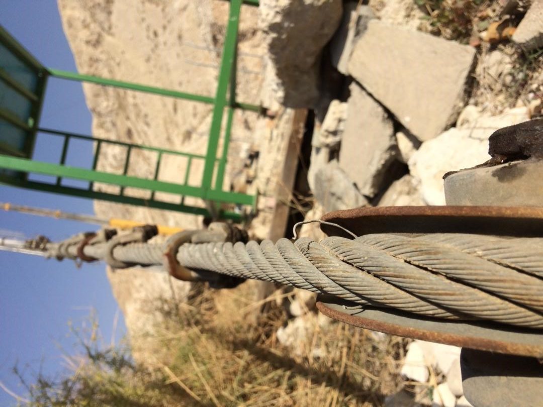
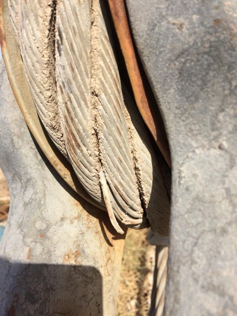
Magnetic Flux Leakage Testing systems are widely used in iron and steel, oil and petrochemical, electric power, shipbuilding, crane cables for the oil, gas, and mining industry (steel cables for piping cranes), and other industries. Magnetic Flux Leakage Test (MFL) is non-destructive.

This test complies with international standards (API, ASME, ASTM &…) is mostly used for pipes, wall and tank roofs, pressure vessels, and magnetized sheets, and due to its ability to inspect with high speed and sensitivity and provide Digital and color printing is an economical method, even from an insulated surface without color picking.
Inspection of the bottom of oil, gasoline, and other fluid storage tanks does not seem economical by ultrasonic means because they are bulky. To increase the efficiency of these tanks, the MFL method is used to inspect pitting corrosion and other floor defects.
The basic principle is that a powerful magnet is used to magnetize the steel. In areas where there is corrosion or missing metal, the magnetic field “leaks” from the steel. In an MFL tool, a magnetic detector is placed between the poles of the magnet to detect the leakage field. Analysts interpret the chart recording of the leakage field to identify damaged areas and hopefully to estimate the depth of metal loss.
Magnetic Flux Leakage Nondestructive Testing System:
Powerful magnetic flux leakage tools saturate a ferromagnetic pipe wall with magnetic flux longitudinally and transversely. In the areas where defects are on inner and outer surfaces or inside of the wall, the magnetic flux “leaks” from these places. Applying the magnetizing field in both directions (orthogonal to each other) can form the leakage flux of the defects at both axial and circumferential directions. The leakage flux is powerful enough to be measured by magnetism-sensitive sensors accurately, these defects will be detected.
This tool is placed around the pipe for inspection. By connecting power to the drive coil, it creates a magnetic field in the component. As the tool moves along the part, changes in wall thickness due to corrosion, erosion, cavitation, etc. will cause the magnetic flux density to change. The received signals are sent to the computer for processing.
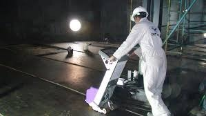
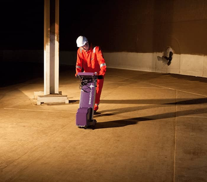
The inspection of the tank floor is the same as for pipes, except that they use a series of magnetic field generators (“bridges”) and sensors. All this equipment is placed on a machine similar to a vacuum cleaner. Stairs produce a saturated magnetic field at the bottom of the tank, and any reduction in thickness or loss of material due to cavities or corrosion can cause anomalies in the shape of the magnetic fluxes, so-called “leakage” magnetically from the bottom of the tank. Slowly These anomalies can be detected by sensors.
Capabilities:
- Sensitive to pitting defect in carbon steels,
- Can be used for thin-walled pipes,
- High-speed inspection at large levels and local corrosion detection,
- Inspection on coated surfaces up to 6 mm thick,
- A method without the need for contact with the surface and thus the interface material,
- Identifiable peripheral cracks,
- Diagnosis of internal or external defects.
Limitations:
- Defects are measured with little accuracy,
- It is very poor at detecting cracks in the longitudinal axis,
- Tubes that are not made of ferromagnetic material can not be tested with this method.
Note: No single inspection method is suitable for inspecting all tubes, and magnetic flux leakage testing is no exception and should be performed by other methods.
Applications:
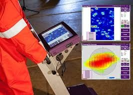
In the range of 6 to 20 mm, all ferromagnetic tank bottoms can be inspected. Furthermore, limited coated surfaces can easily be tested. Based on the MFL/UT data, the tank floor conditions will be reported, which enables the qualified interpreter to evaluate the condition of separate plate levels as well as over the entire floor level in little time. During MFL scans, all indications will be stored along with their location. Bad plates or spots in plates can easily be identified and repaired. In the report, different colors will visualize degradations and concentrations of corrosion.
Conclusions:
MFL equipment has a good capability to detect defects in tank floor plate material.
Large areas of corrosion are more readily detected, whereas isolated corrosion pits are difficult to detect. The worst-case defect missed was a 75% wall loss pit. Nevertheless, it would be difficult for any inspection technique to detect such an isolated defect. The most difficult defects to detect were the small volume ball end pits. Whilst the overall reliability of the technique is good, in situations where corrosion pits are experienced and are significant, in terms of tank floor integrity, then the limitation of the technique needs to be understood. There appears to be little difference between the detection of top and bottom surface defects. The surface condition of the floor plates affects the performance and can result in spurious signals leading to false calls and non-detection. A liner or surface coating does reduce the probability of detection of MFL inspection equipment. Dependent upon the coating thickness the reduction may be significant. In the project trials, a 3.2mm liner not bonded to the plate material surface caused a reduction in the probability of detection of the order of 5%-10%. In practice tank floor liners can be as thin as 1-2mm and should be bonded to the tank floor, thus the effect on the probability of detection will likely be less marked. Increasing the equipment sensitivity will increase the probability of detection, but will also generate more false call indications and vice versa.
False call indications can occur from a variety of sources for the MFL scanning equipment. A follow-up inspection may clarify the source of many such MFL indications, nevertheless, false call indications can remain. End-users need to be aware that false call information can be generated by MFL scanning instruments and the effects that equipment sensitivity and poor surface conditions can have on the levels of false calls. There can be a significant difference in the performance of individuals carrying out any MFL inspection. Thus their approach to MFL inspections must follow the guidelines of the Recommended Practice document to ensure that the thoroughness, coverage, and capability of the inspection are maximized.