INTRODUCTION
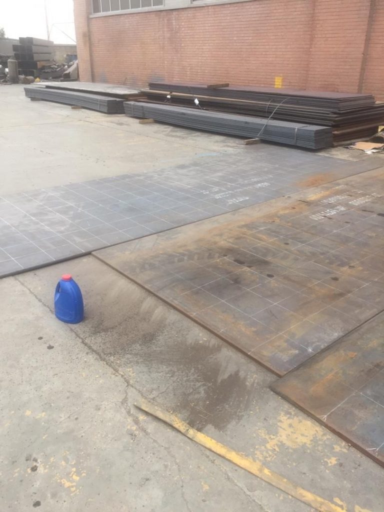
Lamination test is performed to determine and detect defects of parts during the manufacturing process and after manufacturing operations on flat parts. All steels contain nonmetallic inclusions in varying amounts. Hot-rolled steels may contain other internal imperfections such as porosity, seams, or laminations. When the steel is rolled to the desired shape for fabrication, these inclusions and imperfections are elongated in the direction of rolling. Internal seams and tears may or may not be “healed” (welded together by the rolling action).
These defects are likely to occur in thick sections where the mechanical deformation of the internal seams or tears may not be sufficiently worked to “heal” the defects. The specified strength of these steels is always measured in the direction of rolling. The strength of rolled steels in the through-thickness direction (perpendicular to the direction of rolling) is considerably less than the strength obtained in the direction of rolling.
The contraction or shrinkage of deposited weld metal during cooling sets up localized strains in the base metal. These strains may exceed the strength of the base metal in the through-thickness direction, resulting in lamellar tearing. Welds that require the deposition of large amounts of filler metal tend to degrade the tensile properties of the base metal and contribute to lamellar tearing. Highly restrained joints are also susceptible to lamellar tearing and should be welded with caution.
The design of welded joints must take into account the direction of rolling. Welding to members in the through-thickness direction must be avoided, if possible. Where this is unavoidable, the joint should be detailed to reduce the possibility of lamellar tearing resulting from welding. Figure L- 1 illustrates susceptible joint details.
Recognizing lamellar tearing may be difficult since the tearing is internal, like under bead cracking. Corner joints and T-joints are the most susceptible to lamellar tearing, but joint details can be modified to minimize it. If there is any question that subsurface tearing exists, then nondestructive methods should be used to examine the base metal.
A type of discontinuity with separation or weakness generally aligned parallel to the worked surface of a metal. See STANDARD WELDING TERMS. Metal defects with separation weaknesses are generally aligned parallel to the rolled direction of the fabricated section. These defects may result from elongated pipes, seams, or inclusions in the metal that are made directional during the mechanical working of the metal.
- Perform the inspection in an area free of operations that interfere with the proper performance of the test.
- Unless otherwise specified, make the ultrasonic examination on either major surface of the plate.
- The plate surface shall be sufficiently clean and smooth to maintain a first reflection from the opposite side of the plate at least 50 % of full scale during scanning. This may involve suitable means of scale removal at the manufacturer’s option. Condition local rough surfaces by grinding. Restore any specified identification which is removed when grinding to achieve proper surface smoothness.
- Perform the test by one of the following methods: direct contact, immersion, or liquid column coupling. Use a suitable couplant such as water, soluble oil, or glycerin. As a result of the test by this method, the surface of plates may be expected to have a residue of oil or rust or both.
- A nominal test frequency of 2 ¼ MHz is recommended. When testing plates less than 3 continuous total loss of back reflection accompanied by continuous indications on the same plane (within 5 % of plate thickness) that cannot be encompassed within a circle whose diameter is 3 in. [75 mm] or 1⁄4 in. [20 mm] thick a frequency of 5 MHz may be necessary. Thickness, grain size, or microstructure of the material and nature of the equipment or method may require a higher or lower test frequency. Use the transducers at their rated frequency. A clean, easily interpreted trace pattern should be produced during the examination.
A Sample Procedure for Lamination Test
- First, clean the surface of the sample to a suitable level so that the contact between the probe and its surface is well established.
- Use a pulse-echo ultrasonic tester with normal or T/R probes and a frequency of 1 to 5 MHz (preferably 2.25 MHz for the manual method) and a diameter of 25 to 30 mm to perform the lamination test.
- The normal probe is used for thicknesses over 10 mm and the T/R probe is used for thicknesses between 6 to 10 mm.
- The test should be performed on a flat sheet surface. To evaluate the indications, it may be necessary to perform tests from two interrelated levels.
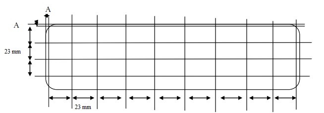
- First, line the surface of the sheet according to the schematic figure as below. Apply a suitable couplant layer on the lines.
- Adjust the sensitivity level of the device so that the first peak reached from the opposite surface of the sheet has a height of 80% of the screen.
- Use the 6 dB drop method to evaluate the indications. After receiving the mark, the defect site should be thoroughly scanned up to a distance of 23 mm on each side.
- The overlap of two adjacent scanning lines must be at least 10%.
- The edges with width A must be completely scanned (value A is taken from the table below). Then line the edge of edge A inwards to a width of 23 mm.
- Scan the longitudinal and transverse lines completely. Any discontinuities that gave the peak a height of more than 50% must be reported.
| width A (mm) | Plate Thickness (mm) |
|---|---|
| 50 | 6<t<50 |
| 75 | 50≤t<100 |
| 100 | 100≤t<200 |
Acceptance Criteria
In this paper, level C represents the highest quality, and level A represents the lowest quality level.
| No. | Level | Defect Description | Equivalent |
|---|---|---|---|
| 1 | A | Any area where one or more discontinuities produce a continuous total loss of back reflection accompanied by continuous indications on the same plane (within 5 % of plate thickness) that cannot be encompassed within a circle whose diameter is 3 in. [75 mm] or 1/2 of the plate thickness, whichever is greater, is unacceptable. | ASTM A578/Grade A |
| 2 | B | Two or more discontinuities of a length equal to or less than the length of the discontinuities of less than 75 mm or 1/2 of the thickness of the sheet (whichever is less) | ASTM A578/Grade B |
| 3 | C | Each type of discontinuity, individually or in groups, has a total length of more than 25 mm | ASTM A578/Grade C |