Abstract
Phased Array technology offers a technical advantage in welding inspection over the old ultrasonic method.
In this method, acoustic radiation has the ability to guide, scan, twist, and focus electronically. Working with this method and replacing it with radiography has benefits, including eliminating the risk of working with radioactive radiation.
Ultrasonic Phased Array Testing capabilities
- Having a permanent document of all inspection and scanning steps
- Inspectors can reinterpret the entire weld length to match the results presented.
- Display A-Scan, B-Scan, C-Scan image on the screen
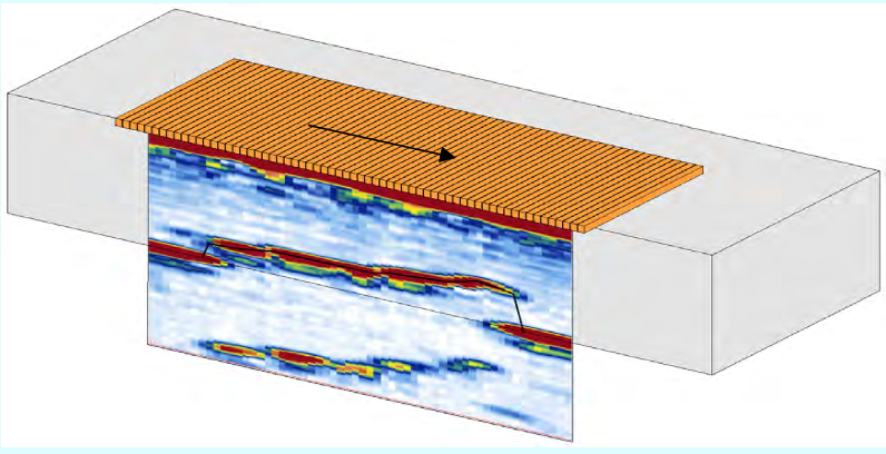
- Along with reports, images of all three scans can be provided as a file or in print. The presence of these images is one of the most important advantages for the proper diagnosis of defects.
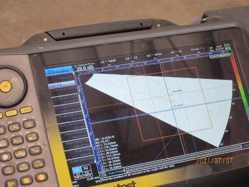
- Display three images End View, Side View, and Top View of the defect
- No need to access both sides of the workpiece

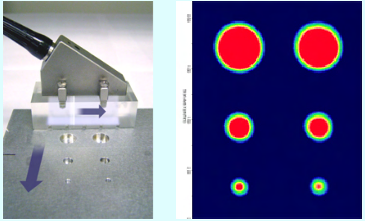
- Ability to accurately check the depth and size of the discontinuity
- Changing the angles of radiation with a probe (by means of electronic refraction tool)
- Ability to inspect complex shapes
- Ability to inspect thick parts
- Changing the angles of radiation with a probe (by means of electronic refraction tool)
- Ability to inspect complex shapes
- Good sensitivity to detect all types of welding defects
- Ability to perform tests at a speed of 10 to 50 meters in one shift and a maximum of 150 meters per day with three shifts
- Ability to submit repair reports based on the limit set by the employer
- Ability to provide full color digital and print reports by system software
Specific inspections can be easily performed with the Phased Array method by adding a beam handle to cover a larger area of the weld, at different angles, symmetrical inspections, or even testing by several tests with several consecutive probes (Tandem Probe) are performed. To use the Fitness For Service technique, we need a very accurate measurement, which is possible using the Phased Array.
The ASME standard has agreed to perform ultrasonic testing with the TOFD welding technique instead of RT for thicknesses greater than 4 inches, and the BS has set the BS standard: 7706-1993 for the TOFD. He pointed out more accuracy in diagnosing and measuring defects and calculating the recorded information. Limitations include insensitivity to defects up to 1.2 inches deep, high cost, and the need for an experienced operator.

In the phased Array and TOFD or AUT method, which is the most accurate inspection method, using a Weld scan XT automatic scanner, a pair of Phased Array probes, and a pair of TOFD probes are used on both sides of the weld. Fully portable with a weight of 3.3 kg and the ability to simultaneously activate 32 elements for each phased Array probe, as well as the ability to scan and process information at very high speeds and can inspect welding positions simultaneously with two different and advanced methods: phased Array and TOFD. Therefore, in general, possible welding defects should show themselves in both methods, and the interpreter can find the defects with a high degree of confidence according to it.

- The Phased Array method, since it is based on ultrasonic radiation, has some limitations, for example, it works poorly to detect porosities or transverse cracks, but it is a suitable method for many linear defects such as LOF, LOP, undercut. In the phased Array method, some defects with specific orientations may not be seen.
- TOFD method since this method is based on diffraction ultrasonic waves and as you are aware, ultrasonic waves are diffracted spherically, in this method all defects can be detected with different orientations. Lack of fusions between the weld pass can only be detected by the TOFD method.
- Simultaneous use of two. The TOFD and phased Array methods use the capabilities of both methods to detect defects and give a 95% confidence interval to detect all welding defects. In these methods, the information will be available to the employer in the form of a computer file with a small volume. Information archiving or documentation is easy.
Standard attention to this method (Ultrasonic Phased Array Inspection) :
- All tank, pressure vessel welding inspection standards such as ASME, BS, ASTM have accepted the above method.
- ASME B31.3 also fully allows the use of computer recorded methods such as TOFD and phased array.
TOFD & Phased array preferable to RT
Preference of TOFD & Phased array over RT It should be noted that the radiographic inspection method has some disadvantages and limitations. For example, in the method of detecting linear defects or different types of cracks, it is difficult that these linear defects are among the most dangerous welding defects, and also dangerous environmental radiation during the inspection is one of the main disadvantages of this method. Restrictions on the inspection of high-thickness parts, as well as consumables such as film and emergence and stabilization materials, lack of gamma resources, and film archives and re-access, are other disadvantages of this method.
- In the AUT method, linear defects such as cracks, LOF, and LOP are far better than radiographic methods. It should be noted that these defects are the most dangerous welding defects that are more difficult to detect with radiography and are not seen in most cases.
- In the radiographic method, the depth of the defect is not determined, while in AUT, the depth and location of the defect, its size, and its exact type are specified accurately. In radiography, the stone must be stoned so that the welder is defective.
- In the radiographic method, there is a need to keep the film as inspection documents, which is why there are problems in keeping the film and reading it, while in the AUT method, the results are provided to the client as an electronic file with the date and time of the test. It can be easily reviewed at any time and a backup can be made.
- The AUT team can be located at a distance of several welding joints from the welding team and if the welders had a poor performance during welding, they are given the necessary warning.
- Since AUT is safe, so no disturbance with the work of the welding team and can check the seams with the same welding speed.
- Due to the existence of consumables in the radiography method and the possibility of changing the price of the film or not importing the appropriate film, the radiography contractor will have problems, but we do not have consumables in the AUT method.
- The ASME standard also allows the use of UT for thicknesses greater than 6 mm.
- In AUT, we see the defect from several views, while in RT, we have only one view, and due to having a three-dimensional image, we can make a better judgment about the defect and the need for repair.