Brief introduction of dry gas seal and related inspections
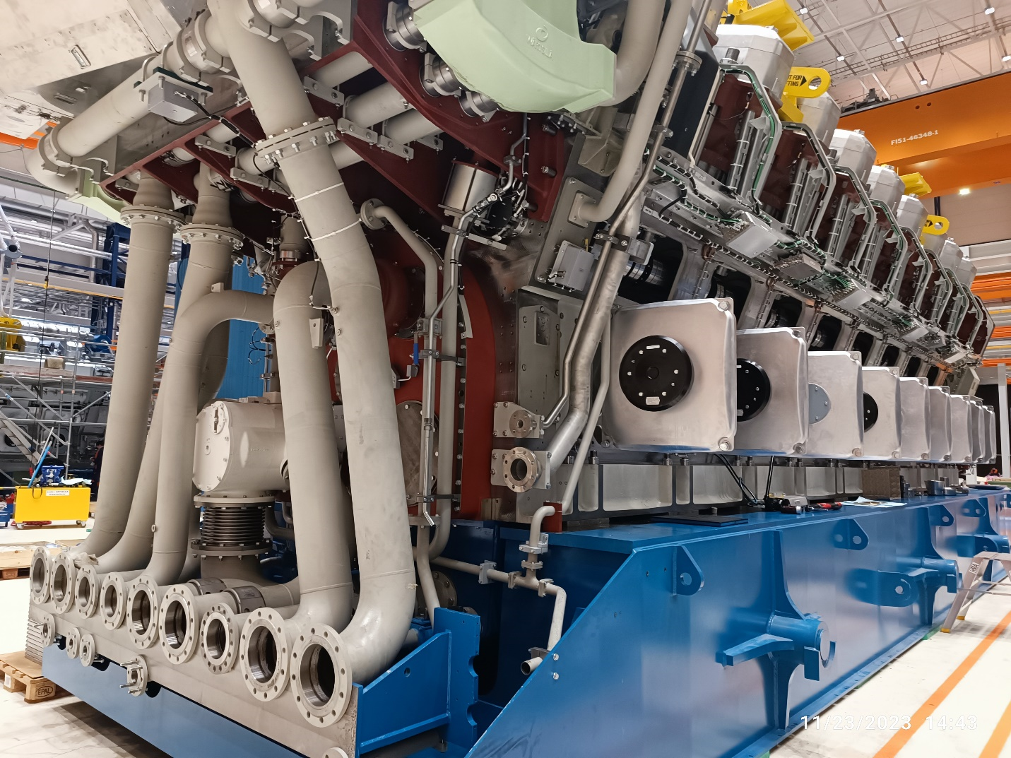
One of the most important components and components of centrifugal compressors that are used in various industries including gas, oil, petrochemical to circulate recycled gas and refineries as condensing and hydrogen compressors are used in reactive systems. They are that due to the almost large pressure difference between the gas inside the compressor and the outside environment if the sealing operation is disrupted, there can be a lot of risks, so their sealing system must be completely safe and have very high reliability.
In low-pressure compressors that compress safe gases, regardless of safety and environmental issues, leakage in terms of energy consumption and noise pollution is also debatable and should be used properly in any case.
Types of sealing systems in compressors
To better understand the Dry Gas Seal, it is best to take a look at older systems to better understand the benefits.
In general, there are two common dry and wet methods in compressor sealing, each of which is divided into several categories:
- Wet method: In this method, despite the main purpose, which is the sealing of gaseous fluid, a liquid fluid is used as a leak-blocking agent. The oil used in the compressor bearing for lubrication is the best option for this and was quickly used in the wet sealing system and had many strengths.
- Dry method: In this method, the interface of the compressor is sealed using interface gas or process gas, so that a limited and specific amount of permissible leakage is considered to control the gas inside the compressor. In this method, there is no moisture in the system and also the absence of oil ensures a clean environment and is free of any liquid hydrocarbons.
Dry Gas Seal: This type of seal, which is the most advanced seal of its kind, can perform sealing work in high-pressure compressors up to 550 bar with high reliability without the presence of oil and using interface gas or process gas. Give. In this system, there is a permanent leak in the predicted and controlled amount, which is a sign of the correct operation of the system.
Advantages of Dry Gas Seals
Dry gas seals, in addition to being able to cover most of the weaknesses of oil floods, also have the following advantages:
- Reduction of sliding friction between sealing surfaces due to gas cushion
- No direct contact with sealing surfaces and no erosion
- Lack of heat production due to surface friction
- Reduction of environmental pollution
- They can withstand the axial movement of the rotor
- Unlike oil seals, if there is a minor problem for one of the seals, this problem does not affect the other side.
The main components of gas seals are:
- Stationery Seal Face
- Rotary Seat
- O-ring
- Spring
- Construction
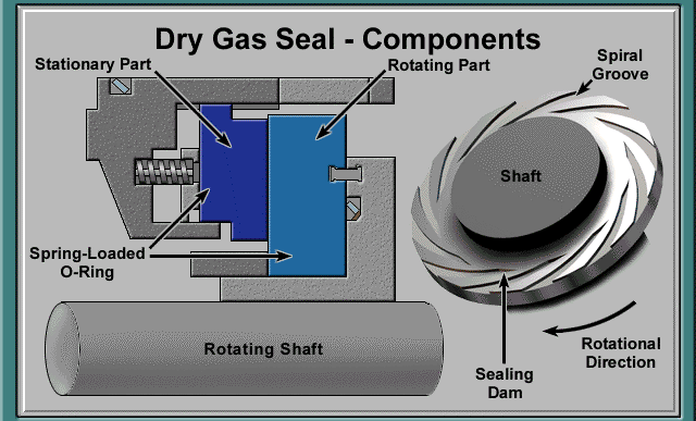
In the above lines, slippery surfaces were mentioned, which is the main difference between mechanical seal and gas seal. These surfaces are the same as Seal Face and Seat, which are placed facing each other in gas seals. And create the least friction. When the compressor is operating, the Seat starts to rotate along the axis and the Seal Face is fixed in front of it. This creates high-pressure pads in the areas between the two slippery surfaces and doubles the distance between them.
Now that we are familiar with the slippery surfaces (Seat & Seal Face), we need to know how these two pieces are placed in their seat inside the gas seal body and are tightened. Yes, you guessed it, this important thing is happening with the O-ring. In gas seals (as well as mechanical seals) O-rings are also known by their functional name, Secondary Sealing Element, because if slippery surfaces are considered as the primary sealing element, they are the second sealing element in O-rings.
Springs are the components that help the Seal Face part, which makes the system stable and facilitates the maintenance of the sealing space between the slippery surfaces. Although springs are small components, they play an important role in the gas sealing system and their damage increases leakage and even Fractures of slippery surfaces.
The gas sealing body is designed as a cartridge and helps to maintain the seal and its easy installation on the compressor because, in the old systems, the sealing systems were produced and installed as separate components, which is an error in the installation of each component. This would result in a malfunction of the entire assembly, while the new body would be installed seamlessly, greatly reducing installation errors.
ACTIVITY / KIND OF TESTS
- Material Conformity
- Performance test (Static and dynamic acc. API 617 Part 1 Annex F)
- Over speed test of Dry Gas Seals
- Test of separation / Barrier Seals
- Material traceability
Understanding Seal Gas Supplies to Dry Gas Seal
- Primary Seal
- Primary Seal Gas is, typically, Filtered gas from the compressor discharge side, injected into the Seal Chamber (the primary inboard seal chamber)
- A major part of this injected gas will flow back to the compressor through the inner labyrinth at the process gas side.
- This achieves the prevention of emissions from the compressor to the atmosphere.
- A small quantity of gas will pass through the dynamically separated gap of seal faces to the intermediate chamber between the inboard &outboard seals
- Since this cavity is vented, the rate ( quantity per minute) of gas flowing out is measured downstream.
- This is the indication of the leakage rate of the seal.
- A minimum rate of leakage will be always present. Increase in the rate of leakage beyond design limits indicates reduced seal performance/ Efficiency
- Secondary Seal ( Containment seal )
- Secondary Seal is a backup seal that seals the leakage from the primary seal chamber
- Nitrogen is injected into this secondary Seal Chamber
- The Secondary Seal Functions as a safety seal to avoid emissions to the atmosphere in case of excessive leakage in the primary seal
- Separation seal ( Barrier seal)
This seal also works in conjunction with a separation labyrinth situated between the bearing housings and Seal Chambers- The separation gas is also Nitrogen, injected into the separation labyrinth
- The main purpose of the Separation gas supply is to prevent the oil in the bearing side from entering the seal Chamber.
- The presence of oil in the seal chamber will cause damage to the Dry gas seal components
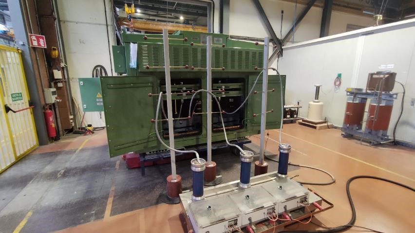
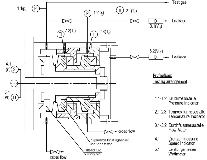
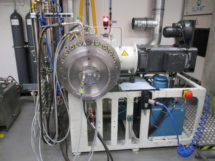
Gas seal testing is performed in a special test facility, and both gas seals (from opposite ends of the compressor rotor) are tested simultaneously. The gas seal test facility typically includes:
- variable speed electric motor driver
- speed increasing gear
- test vehicle (pressure chamber)
- seal gas supply system
- control panel
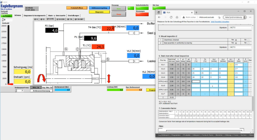
- data acquisition system
As with balancing, the exact gas seal testing procedure and acceptance criteria may be defined by the compressor manufacturer or the purchaser of the compressor. In the absence of such customer requirements, each gas seal manufacturer has its testing procedures, standards, and acceptance criteria. API617, the 8th Edition, Annex 1F, provides an industry standard for gas seal verification testing and specifies the following test procedure.

Static testing steps
- Establish the primary seal gas pressure at the maximum specified static sealing pressure.
- Hold this pressure for a minimum of 10 minutes and record data.
- Reduce the primary seal gas pressure to 75% of the maximum specified static sealing pressure.
- Hold this pressure for a minimum of 10 minutes and record data.
- Controlling the Repeat steps 3 and 4 at 50% and 25% of the maximum specified static sealing pressure.
Dynamic testing steps
- Establishing the primary seal gas at the maximum specified pressure and temperature, and the primary vent at the minimum specified backpressure.
- Increasing the speed from zero to the maximum continuous compressor operating speed.
- Checking the Maintain this speed for a minimum of 15 minutes, or until the primary seal leakage reaches a steady-state, and record data.
- Increasing the speed to compressor trip speed.
- Checking the Maintain this speed for a minimum of 15 minutes, recording data every five minutes.
- Reduce the speed to the maximum continuous compressor operating speed.
- Checking the Maintain this speed for a minimum of 60 minutes, recording data every 5 minutes. The average primary seal leakage must be less than the maximum specified primary seal leakage.
- Increase the primary vent back pressure to the maximum value specified.
- Checking the Maintain this primary vent backpressure for a minimum of 15 minutes, and record data.
- Increase the primary vent back pressure to the maximum specified seal gas pressure.
- Checking the Maintain this primary vent backpressure for a minimum of 15 minutes, recording data every 5 minutes.
- While maintaining the pressure, shut down the test rig to a complete stop.
- Restart and accelerate to maximum continuous compressor operating speed, and then to compressor trip speed, as quickly as possible.
- Reduce speed back to maximum continuous compressor operating speed.
- Checking the Maintain this speed for a minimum of 5 minutes, or until the primary seal leakage reaches a steady-state, and record data.
- Repeat steps 12 through 15.
- Shut down the seal test rig while maintaining gas conditions.
- Record two sets of data immediately after shutdown.
Visual inspection
- Upon completion of the dynamic test, disassemble the gas seal and observe the condition of the parts, noting wear patterns or buildup of material.The visual and appearance of supplied items will be check and no visual defects are observed and also the entire brand was found new. Cleanliness must be checked. All parts must be without faults.
- Document the observed condition of the gas seal components.


Static test verification
- Reassemble the gas seal.
- Repeat the static testing procedure.
Report
The vendor must be issue a detailed test report. This report must be documented test run parameters including time, speed, and leakage rates.