This is an article about test of control valve. In the previous part of this article we talked about the types of control valves, different parts of a control valve, working principles, as well as visual and dimensional checks. In this part of the article, we look at other things, such as chemical analysis and pressure tests.
Read Inspection and Testing of a Control Valve – Part 1
5- PMI test of chemical analysis
PMI test can be implemented on bulk piping, plate materials (pressure parts and attachments), and fabricated components of the control valves to determine nominal chemistry and material classification. The Portable X-ray Fluorescence (XRF) method shall be used unless analysis for carbon content is required.
When analysis of carbon content is required, the acceptable methods are:
- Portable Optical (Arc) Emission Spectrometry (OES). A liquid penetrant examination of the test area shall be conducted after the PMI test.
- Wet Metallurgical Analysis by laboratory testing
The acceptance criteria for the PMI test are usually established as per the applicable ASTM material code.
6. Pressure Tests
For proper working of control valves, there are some tests that commonly include pressure tests (hydrostatic or shell tightness tests, seat/plug/packing leakage tests), functional and operational tests.
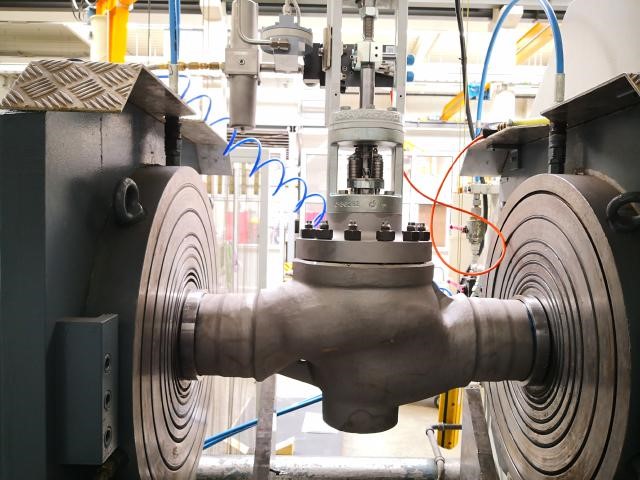
a) Hydrostatic (shell/body) test
Hydrostatic testing proves the structural integrity and leak tightness of the valve’s pressure-containing parts. The hydrostatic shell test is performed to confirm the pressure-containing capability of the shell against internal pressure and to confirm the leak tightness of the shell including the operating mechanism sealing against internal pressure.
New valves and valves which have gone through a full reconditioning process need to be body tested with liquid at 1.5 times the nominal working pressure. Prior to the hydrostatic body or so-called Shell test, the valve is usually filled by tilting the clamp or by a ‘vacuum–filling’ system. Visual inspection and/or a pressure decay method are used to prove the body’s integrity.
The hydrostatic test is mostly conducted as per ASME B 16.34 or MSS-SP61. For the body, the output of the control valve is test blinded using a blind flange. The valve should be fully opened in a position of either the control valve is NO or NC. It should be open at the time of the test. The other important parameter to check is the body rating of the control valve.
Body rating is the amount of total pressure which the body and stem seal can withstand without leaking.
- If the body rating is 300 psi
- The pressure of water that should give through the inlet of the control valve is 300 * 1.5 = 450 psi
- With the help of the pump produce 450 psi in the control valve and with the help of master gauge we can make sure that pressure is 450 psi
- Then close the mechanical valve.
- Check whether any leakage of water through the outlet of the control valve.
- If there is no leakage the body test is passed.
b) Plug/Seat/Packing leakage test
The seat leakage test is carried out to confirm the capability of the seat(s) to conform to the specified leakage rate. Seat Leakage testing proves the acceptability of the valve’s closure mechanism. Seat leakage test is mostly performed as per ANSI/FCI 70-2.
- For the flow test outlet of the control, the valve should be open
- The valve should be fully closed
- The procedure is the same as body test
- Apply 450 psi to the valve and check for any leakage.
- If there is leakage, i.e., due to trim damage, seat ring damage, actuator, and valve stem are not properly connected and aligned.
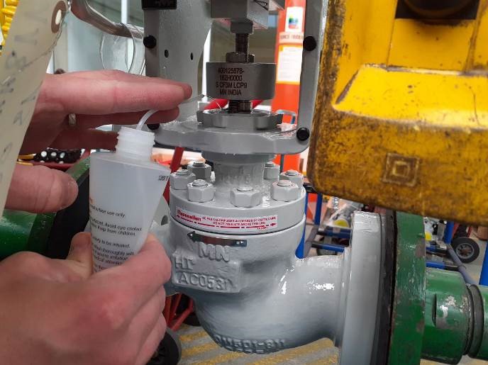
The seat leakage is tested with gas or liquid according to the international test standards. The most common applied test standard is ANSI/FCI 70-2. Control valves class I – IV and VI are tested with gas. Class V with liquid.
The seat leakage is measured on the in or outlet side by the digital calibrated flow measuring system. The leakage (displayed in ln/min, ln/h, scfh, or bubbles/min) is automatically compared with the standardized allowed leakage, followed by pass/fail signal.
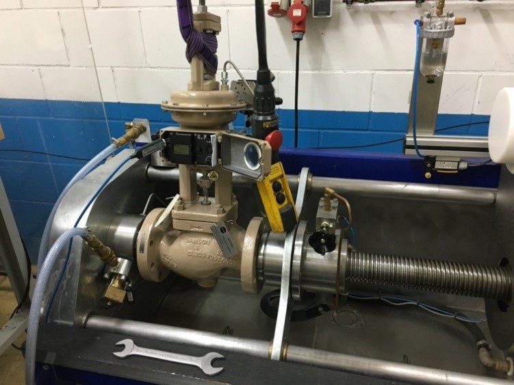
c) Functional and Performance test
Control valve functional and operational tests are usually conducted as per IEC 60534-4 and ISA 75.13.01. the purpose of these tests is to check whether the valve is properly assembled and working correctly and according to the technical specifications and guaranteed requirements.
For checking the function of a control valve, the valve, i/p converter, current generator, and instrument air supply are set up. The instrument air supply is checked. It is set according to the i/p converter requirements. 4 mA current signal is applied to the i/p converter the valve stem shall be in 0% travel. When 20 mA is applied 100% travel should be done. If the valve stem travel indication didn’t show correctly then calibration is to be done.
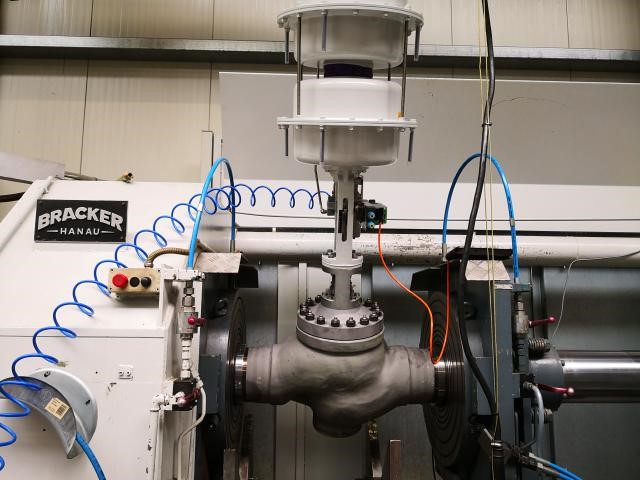
Travel Test, Stroke test:
This test method is used for demonstrating that the actuator has an adequate force to open and close the valve. The procedure shall demonstrate that no mechanical damage or permanent deformation of valve components will occur and that accessories function properly
The functionality of the control valves is tested and adjusted according to the manufacturer’s specification or specific process circumstances. The valve is operated to the open-/close position by operating the actuator and/or positioner with external signals, usually 0 – 21 mA / 0-20 PSI / 0-100 PSI. Specific software for digital positioners can be applied.
Hysteresis test plus dead band
Dead band plus hysteresis is a static measurement that can be estimated using a quasi-steady‐state test signal. All tests are performed using standard digital valve controller diagnostic procedures with the cutoffs and characterization disabled and with the travel integrator disabled. This is done to prevent limit cycles, overshoots, or other transients that would invalidate the dead band plus hysteresis estimate.
The dead band plus hysteresis test consists of series of steps that slowly move the valve in the opening and closing directions. The dead band plus hysteresis test consists of two sequences. The first sequence is a break‐in cycle that moves the valve through its dead band and establishes a valid starting point for the second sequence. Data from the break‐in cycle are not analyzed. The second sequence is the test cycle and data from this sequence are used to estimate dead-band plus hysteresis.
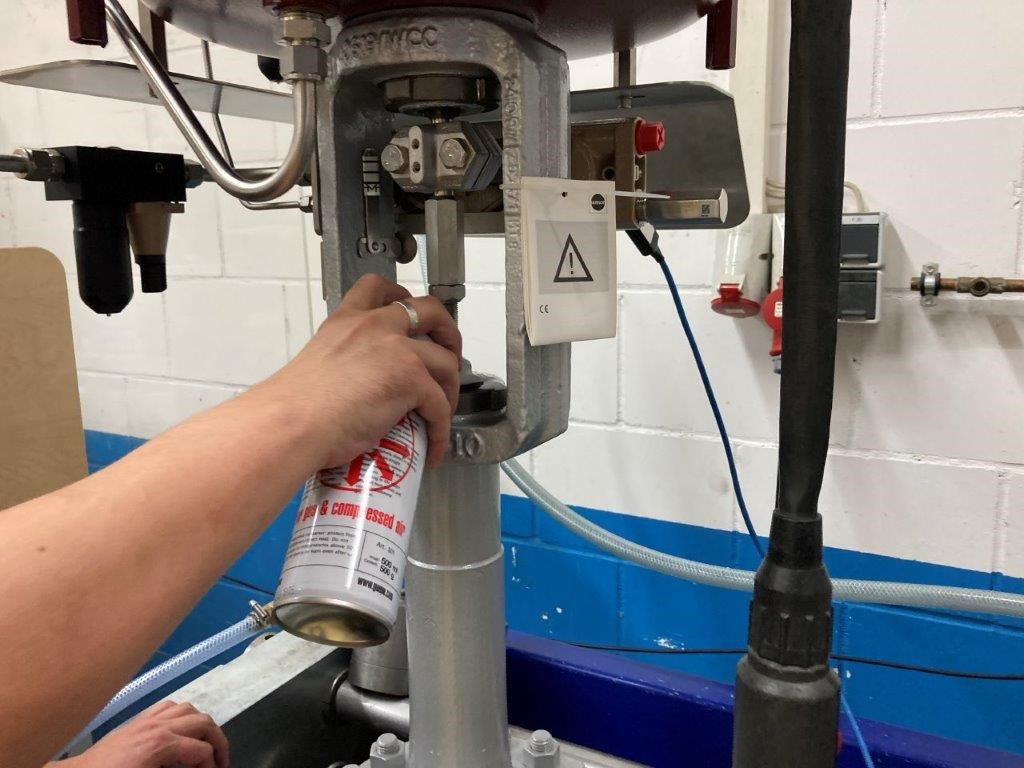
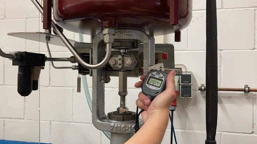
Response time measurement
The response time of a solenoid control valve is defined as the amount of time needed for a valve to go from an open to a closed position or vice versa. Indeed, the response time at energizing is not equal to the response time at de-energizing for solenoid valves, especially when an alternating current is used. The C.E.T.O.P. (the European Fluid Power Committee) defined a standard measurement procedure to define the response time for solenoid valves. However, bear in mind that many valve manufacturers use alternative definitions or measurement procedures. For the valve opening, the response time is defined as the duration between energizing the solenoid and reaching 90% of the stabilized outlet pressure. The response time for closing the valve is defined as the duration from de-energizing the solenoid until the pressure drops to 10% of the test pressure. The test is executed with air at 6 bars at 20°C.
Functional Test of Electrical Accessories (such as solenoid valve, actuator, positioner, I/P positioner, etc.)
To keep valves operating properly, you need to periodically check electronic valve positioners. However, these checks need to be conducted quickly to minimize downtime. If calibration drift is found, the valve positioner must also be recalibrated immediately.
A good tool for this is a source meter or a handheld field tester like the Fluke 789 ProcessMeter that can be used to test and re-calibrate electronic valve positioners. It offers signal sourcing to simulate a controller connected to a valve positioner’s input and can continuously adjust the source current in incremental steps, so you can check the valve’s linearity and response time.
Painting Inspection
The finished paint is checked by the inspector to make sure about the visual quality of the painted parts correct shade, degree of gloss and evens, and being freed from paint visual defects such as tackiness after drying/curing, cracks, holidays, runs, sags, wrinkles, patchiness, brush or roller marks, or other defects that may be deleterious to the quality of the coating.
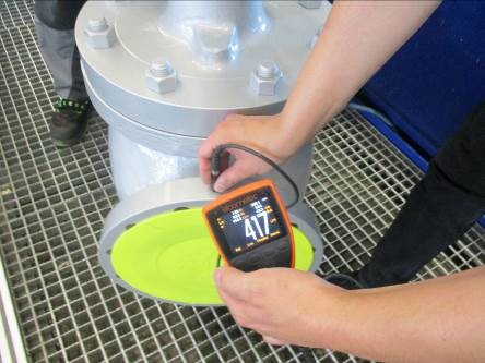
The total dry film thickness (DFT) of the paint over valves parts such as body, flange and actuator are checked in accordance with reference painting system/specification and manufacturer procedure and by using a calibrated magnetic probe (such as Elcometer) and the measured values are compared with the allowable thicknesses range.
The painting color shade is controlled and verified to be correct as per the RAL color code determined in the painting system and specifications.